
Tire blank three-dimensional truss robot automatic conveying line

A three-dimensional truss and automatic conveying technology, which is applied to tires, household appliances, and other household appliances, can solve the problems of high physical labor intensity, low production efficiency, and easy pollution of embryos

Pending Publication Date: 2017-10-10
HEFEI WANLI TIRE CO LTD
View PDF5 Cites 2 Cited by
  • Summary
  • Abstract
  • Description
  • Claims
  • Application Information

AI Technical Summary

Problems solved by technology

[0003] 2. At present, it is known that the embryo after molding is placed on the embryo tray or embryo transfer vehicle, pushed to the vulcanizing machine by forklift or battery trailer or manually, and then manually transported to the tire storage device of the vulcanizing machine, especially the production weight is very large When using all-steel tires, the physical labor intensity is high, the production efficiency is low, the embryos are easily polluted, and there are problems of moving the wrong tires.

Method used


Image

  • Tire blank three-dimensional truss robot automatic conveying line
  • Tire blank three-dimensional truss robot automatic conveying line

Examples


Embodiment 1

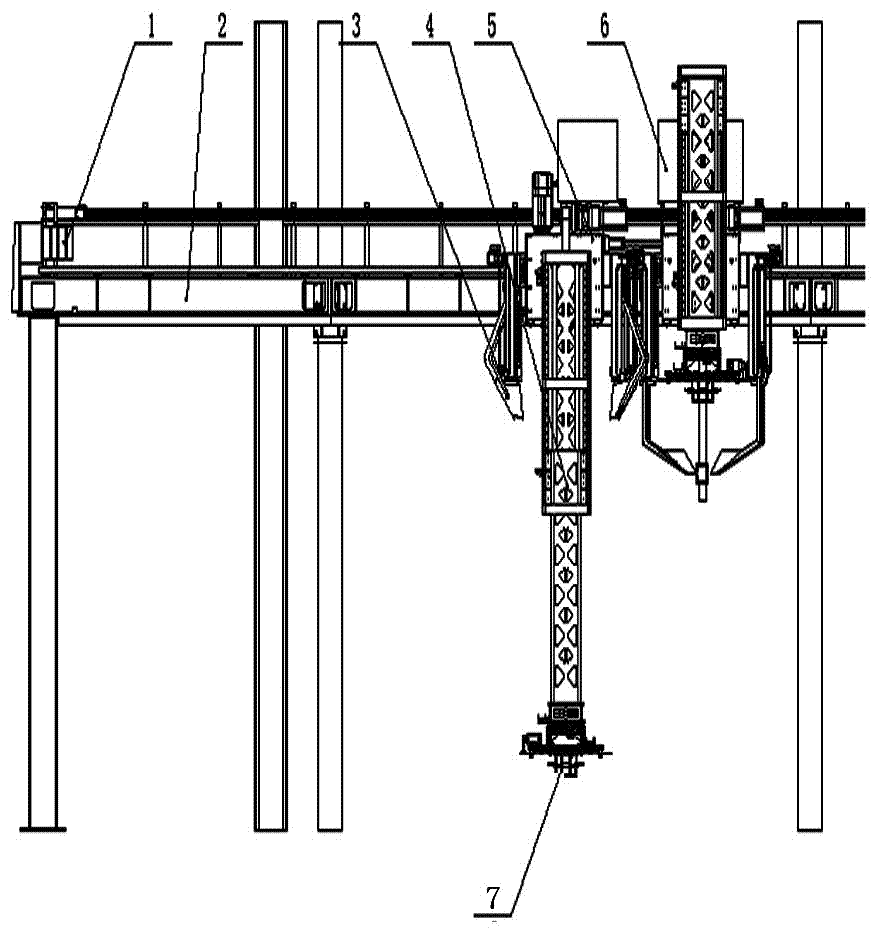
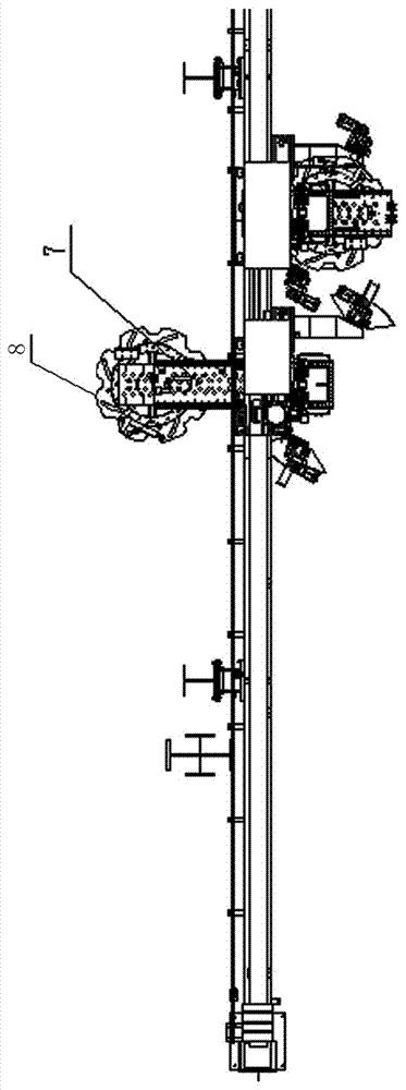
[0019] The tire blank three-dimensional truss robot automatic conveying device of the present invention comprises a walking guide rail 2, a walking device 5, a lifting hydraulic device 4, a tire gripping manipulator and an electric control box 6, and the walking device 5 includes a slider and a fixed connection thereto. stand. The walking guide rail 2 is erected horizontally in the air, the bracket is arranged parallel to the walking guide rail 2, and is connected with the walking guide rail 2 through a slider, and the lifting hydraulic device 4 is arranged vertically to the walking guide rail 2. The lifting hydraulic device 4 includes a movable truss, a fixed truss and a lifting hydraulic cylinder, the movable truss is sleeved inside the fixed truss, and is movably connected to the fixed truss through the lifting hydraulic cylinder. The tire gripping manipulator comprises a motor, a rotary chuck 8, a fixed plate, an electric cylinder and several tire claws 7, and the rotary c...

Embodiment 2

[0024] This embodiment is basically the same as Embodiment 1, except that a sliding guide rail is symmetrically arranged on both sides of the fixed truss in this embodiment, and a second sliding rail is respectively provided between one end of the two sliding guide rails and the fixed truss. block, one end of the two sliding guide rails is respectively retractable on the second slider, and the two sliding guide rails are movably connected with the fixed truss through the second slider; The tire claws 7 are arranged between the two tire protection baffles 3, and the projections of the two tire protection baffles 3 on the horizontal plane are arc-shaped. The centers of circles surrounded by projections on the same horizontal plane coincide; expansion and contraction hydraulic cylinders are respectively arranged between the two sliding guide rails and their corresponding second sliders.

[0025] Present embodiment is provided with two tire protection baffles 3 on the outside of g...

Embodiment 3

[0027] This embodiment is basically the same as Embodiment 1 or Embodiment 2, the difference is that the other ends of several tire gripping claws 7 described in this embodiment away from the claws are respectively rolled up, and this structure can make the tire gripping claws 7 grasp When picking up the embryo, hook up the inner wall of the embryo to achieve a reliable grasping action.


PUM


Abstract

The invention relates to a tire blank three-dimensional truss robot automatic conveying line for a tire vulcanization process. The tire blank three-dimensional truss robot automatic conveying line comprises a travelling guide rail, a travelling device, a lifting hydraulic device, a tire grasping manipulator and an electric control box; the travelling guide rail is horizontally erected in air; the travelling device is movably arranged on the travelling guide rail; and the lifting hydraulic device is perpendicular to the travelling guide rail. The automatic conveying line has the following beneficial effects that (1) tire blanks are grasped in pairs and automatically conveyed to a vulcanization machine tire storage device, the vulcanization labor intensity is relived, and the production efficiency is improved; and (2) the production automation degree of a vulcanization workshop is increased, and the production cost is reduced.

Description

technical field [0001] The invention relates to an automatic conveying line of a three-dimensional truss robot for a tire blank used in a tire vulcanization process. Background technique [0002] 1. The tire production line mainly includes ingredients, components, molding, vulcanization, inspection and warehousing and other processes. The quality of the molded tire directly affects the quality of the finished tire after vulcanization, so there are many more stringent process requirements; [0003] 2. At present, it is known that the embryo after molding is placed on the embryo tray or embryo transfer vehicle, pushed to the vulcanizing machine by forklift or battery trailer or manually, and then manually transported to the tire storage device of the vulcanizing machine, especially the production weight is very large When using high-quality all-steel tires, the physical labor intensity is very high, the production efficiency is low, the embryos are easily polluted, and there a...

Claims


Application Information

Patent Timeline
IPC IPC(8): B29D30/00
CPCB29D30/0016B29D2030/0038
Inventor 贺建浩石峥李承民王晓磊刘世显张目陶海邹业杜可栋
Owner HEFEI WANLI TIRE CO LTD
Learn More