Railway tunnel automatic deicing device and method

A tunnel and automatic technology, applied in the direction of overhead installation, cable installation, electrical components, etc., can solve the problems of workers' life safety hazards, economic losses, invasion, etc., to reduce manual inspections and ice, save labor costs, and ensure safety sexual effect

Pending Publication Date: 2017-10-10
SOUTHWEST JIAOTONG UNIV
View PDF0 Cites 8 Cited by
  • Summary
  • Abstract
  • Description
  • Claims
  • Application Information

AI Technical Summary

Problems solved by technology

In 2008, the southern part of our country suffered from a freezing weather disaster that had never happened in a century. Icing appeared in many tunnels, and the icing invaded the catenary, which made many electrified railway lines in the south paralyzed. They had to rely on dispatched diesel locomotives for rescue, causing serious damage. economic loss and social harm
[0004] Tunnel ice damage has always been a hot topic in the engineering field. The existing method of removing ice hanging from tunnels mostly adopts manual inspection and ice breaking on a regular basis. This method requires investment A large amount of manpower, and for the maintenance workers, the working environment is harsh and dangerous, which is a potential hazard to the life safety of the workers
There are also some railway bureaus who have adopted the method of transforming tunnels and using electric energy to melt ice to eliminate the impact of ice damage. However, this method requires an astonishing investment, a long construction period, and a huge consumption of resources.

Method used


Image

  • Railway tunnel automatic deicing device and method
  • Railway tunnel automatic deicing device and method
  • Railway tunnel automatic deicing device and method

Examples


Embodiment Construction

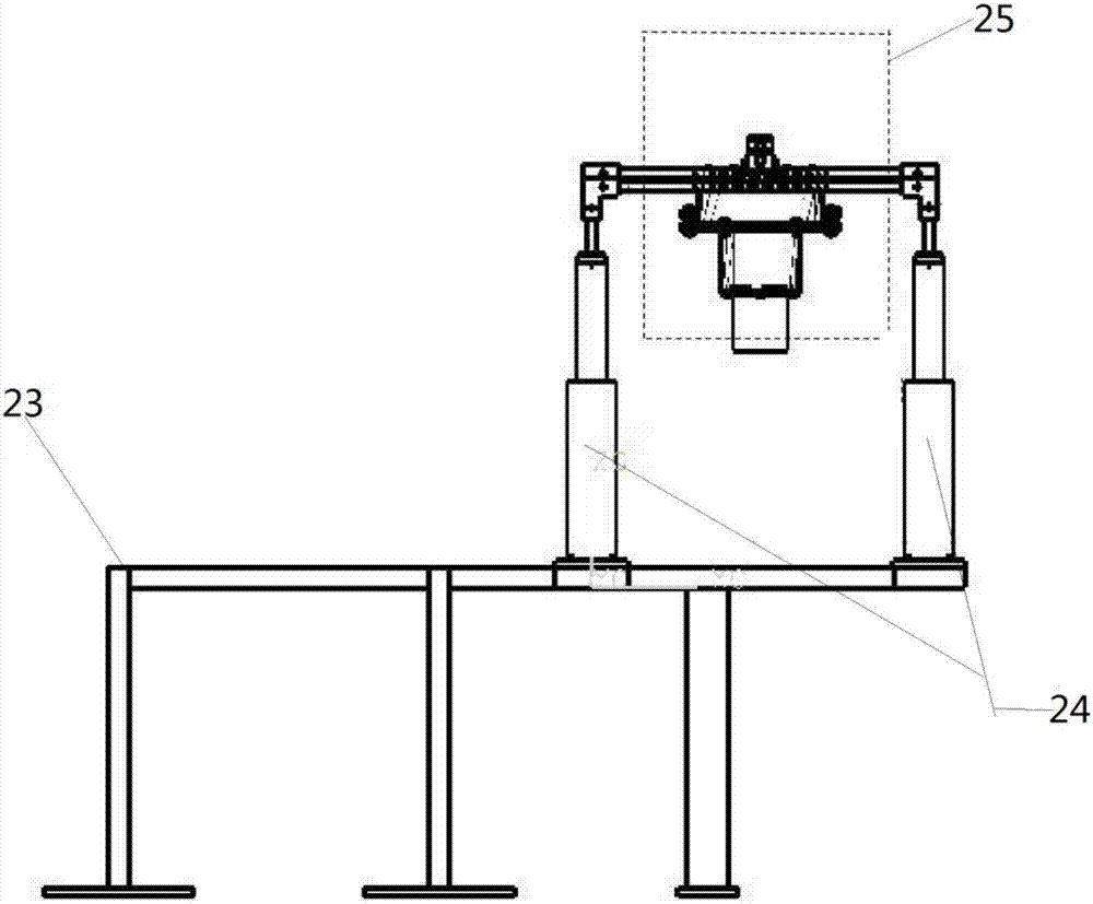
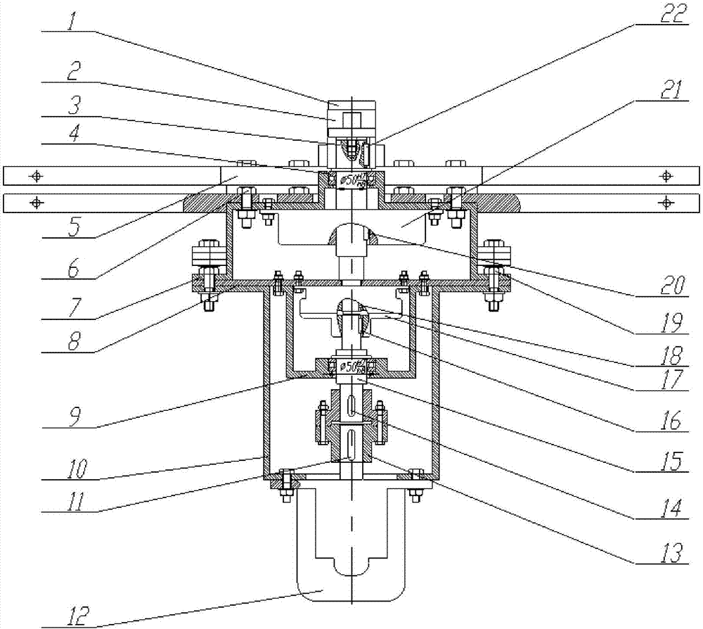
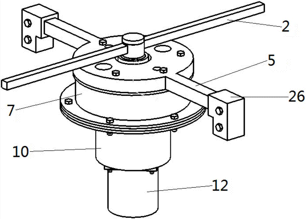
[0026] figure 2 Show this railway tunnel automatic deicing device, be used to be installed on the platform of the base support assembly 23 of train roof front end, be installed with two groups of synchronous hydraulic cylinders 24 in vertical direction, the left and right sides of the suspension frame 5 in horizontal direction The ends are correspondingly fixed on the tops of the two piston rods of the two groups of synchronous hydraulic cylinders 24; the deicing action mechanism 25 is fixed on the suspension frame, and the deicing action mechanism 25 is: the shaft of the servo motor 12 in the vertical direction passes through the shaft coupling The device 13 is connected with the No. 2 shaft 15, the No. 2 shaft 15 is used as the transmission main shaft and connected with the driving end of the electromagnetic clutch 17, the lower end of the No. 1 shaft 3 is connected with the driven end of the electromagnetic clutch 17, and the middle part of the deicing rod 2 is fixed on the...


PUM


Abstract

The invention provides a railway tunnel automatic deicing device and method. A platform of a base support assembly (23) used for being installed at the front end of the top of a train is provided with two sets of synchronous hydraulic cylinders (24) in the vertical direction, and the left end and the right end of a suspension frame (5) in the horizontal direction are correspondingly fixed on the tops of two piston rods of the two sets of synchronous hydraulic cylinders (24); a deicing action mechanism (25) is fixed on the suspension frame; according to the deicing action mechanism (25), a vertical shaft of a servo motor (12) is connected with a second shaft (15) through a coupler (13), the second shaft (15) serves as a transmission main shaft to be connected with the driving end of an electromagnetic clutch (17), the lower end of a first shaft (3) is connected with the driven end of the electromagnetic clutch (17), and the middle of a deicing rod (2) is fixed on the top of a first shaft (3). The device has the advantages that the structure is simple, tunnel deicing can be carried out by utilizing kinetic energy of the train, manpower and financial resources are saved, and the device is particularly suitable for automatic control and the like.

Description

technical field [0001] The patent of the present invention relates to mechanical deicing equipment for maintenance of electrified railways, in particular to a deicing device on the top of electrified railway tunnels. Background technique [0002] Since my country built the first electrified railway Baocheng Line in 1958, after decades of rapid development, the total mileage of my country's electrified railway exceeded 48,000 kilometers in 2012, surpassing the second place Russia and ranking first in the world. A large number of tunnels are produced during the construction of electrified railways. With the increase of railway operation time and changes in external geological conditions, water seepage and leakage will inevitably occur in tunnels. In areas with lower latitudes or in summer, tunnel water seepage has little effect on the operation of railway trains, but in cold seasons, especially in some high latitude areas, the problem of tunnel water seepage poses a great safe...

Claims


Application Information

Patent Timeline
IPC IPC(8): B60M1/28H02G7/16
CPCH02G7/16B60M1/28Y02A30/30
Inventor 吴文海郭通于兰英孙磊
Owner SOUTHWEST JIAOTONG UNIV
Why Eureka
Try Eureka