
Multi-cylinder engine cylinder hole ceramization clamp, device and method

A multi-cylinder engine, ceramic technology, applied in the direction of anodic oxidation, electrolytic coating, surface reaction electrolytic coating, etc., can solve the problem of low cylinder bore roundness and cylindricity accuracy, poor cylinder bore surface roughness, and cylinder bore roundness , cylindricity accuracy has not been improved, etc., to achieve the effect of improving product quality, satisfying cylindricity, and improving quality

Inactive Publication Date: 2017-10-10
GREAT WALL MOTOR CO LTD
View PDF10 Cites 7 Cited by
  • Summary
  • Abstract
  • Description
  • Claims
  • Application Information

AI Technical Summary

Problems solved by technology

But at present, there is still no special fixture suitable for the ceramization process of the engine block, which makes the ceramization process of the automobile engine block very inconvenient in actual production, and restricts the promotion of the ceramization process of the cylinder block
[0004] In addition, after ceramicization, in the 50-60 μm thick ceramic layer formed in situ in the cylinder hole, there is a 5-10 μm loose layer on the surface, which will make the surface roughness of the cylinder hole poor, and the cylinder hole round The accuracy of the degree and cylindricity is low. If it is not processed, it cannot meet the product accuracy requirements of the automobile engine block.
At present, the loose layer on the surface of the ceramic layer is mostly polished with soft materials such as sandpaper or nylon, which can remove the loose layer to improve the roughness of the cylinder bore, but has no effect on the roundness and cylindricity accuracy of the cylinder bore. Moreover, the efficiency of the existing polishing method is very low, and it cannot meet the high-efficiency production requirements of the engine batch

Method used


Image

  • Multi-cylinder engine cylinder hole ceramization clamp, device and method
  • Multi-cylinder engine cylinder hole ceramization clamp, device and method
  • Multi-cylinder engine cylinder hole ceramization clamp, device and method

Examples


Embodiment 1

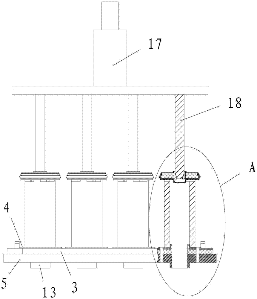
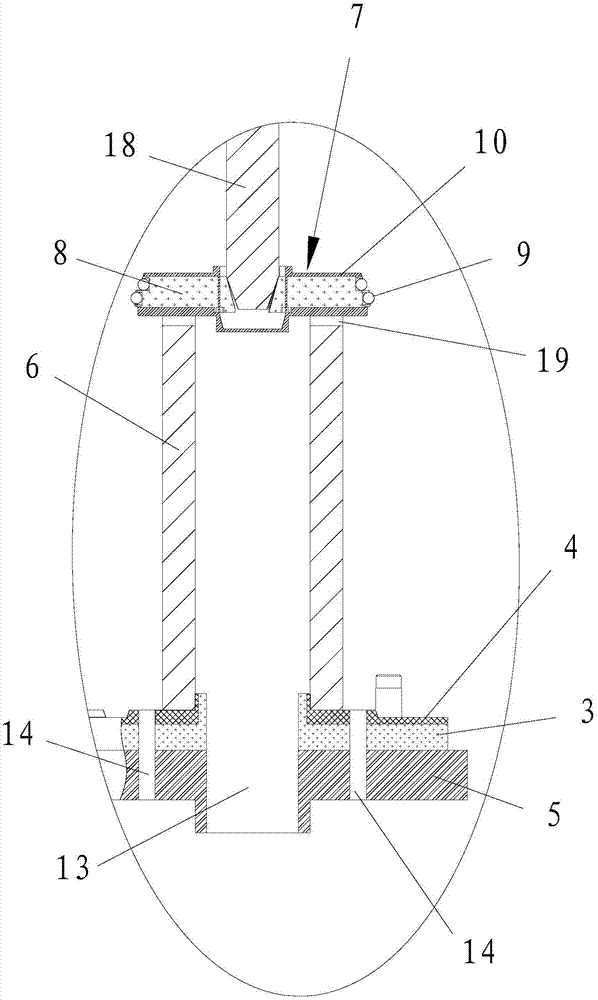
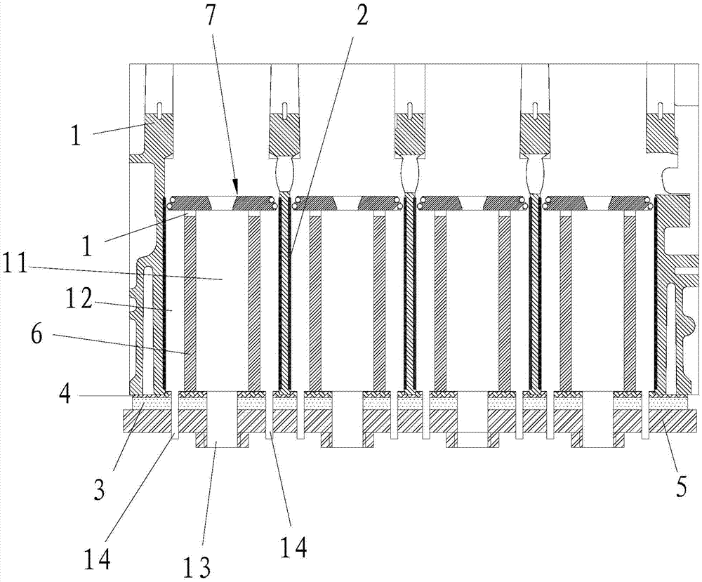
[0037] This embodiment relates to a fixture for ceramicizing cylinder bores of a multi-cylinder engine, consisting of figure 1 , figure 2 and combine image 3 As shown, the multi-cylinder engine cylinder hole ceramization fixture includes a bottom plate 5, and a cylinder hole top sealing plate 4 fixedly connected to the bottom plate 5, and an insulating plate is also sandwiched between the bottom plate 5 and the cylinder hole top sealing plate 4. 3. The insulating plate 3 can realize electrical insulation between the bottom plate 5 and the cylinder block 1 of the multi-cylinder engine, so as to avoid electric leakage. The multi-cylinder engine cylinder hole ceramization fixture also includes a cylinder hole bottom sealing plate 7 arranged above the cylinder hole top sealing plate 5, and the quantity is corresponding to the number of cylinder holes 2 on the multi-cylinder engine cylinder block 1, and setting In the cylinder hole 2, the cathode electrolysis part 6 is press-fi...

Embodiment 2

[0044] This embodiment relates to a multi-cylinder engine cylinder bore ceramic device, such as Figure 4 As shown in , it includes an electrolyte tank 16 and a power supply 15, and also includes a multi-cylinder engine cylinder bore ceramization fixture as described in Embodiment 1, and the multi-cylinder engine cylinder block 1 is clamped on the multi-cylinder engine cylinder bore ceramization fixture , the electrolyte tank 16 forms a liquid inlet passage through the liquid inlet 14 and the liquid inlet chamber 12, and the electrolyte tank 16 is also connected with the liquid outlet 13 to form a liquid outlet passage. Through the liquid inlet passage and the liquid outlet passage, the The electrolyte containing electrolyte in the electrolyte tank 16 continuously enters the liquid inlet chamber 12 . The positive pole of the power supply 15 is electrically connected to the cylinder block 1 of the multi-cylinder engine, and the negative pole of the power supply 15 is electrical...

Embodiment 3

[0047] This embodiment relates to a multi-cylinder engine cylinder bore ceramization method, the method comprises the multi-cylinder engine cylinder block 1 clamped in the multi-cylinder engine cylinder bore ceramization device as described in the second embodiment of the multi-cylinder engine cylinder The ceramicization process has been performed on the hole ceramicization jig. In addition, the multi-cylinder engine cylinder hole ceramization method further includes the step of honing the cylinder hole 2 after the ceramization treatment, and the honing step uses a rough honing to remove the 15-20 μm allowance in the diameter direction of the cylinder hole 2 Finally, a fine honing is also carried out to remove the diameter of 5-10 μm in the diameter direction of the cylinder bore 2.

[0048] Specifically, the multi-cylinder engine cylinder bore ceramization treatment steps in this embodiment include:

[0049] (1) Carry out rough boring and fine boring on the inner wall of the...


PUM

PropertyMeasurementUnit
Cylindricityaaaaaaaaaa
Roundnessaaaaaaaaaa

Abstract

The present invention provides a multi-cylinder engine cylinder hole ceramization fixture, comprising a bottom plate, a cylinder hole top sealing plate formed on the bottom plate, and a cylinder hole bottom sealing plate formed above the cylinder hole top sealing plate. A cathode electrolysis part with a cavity formed inside is press-fitted between the sealing plate at the top of the cylinder hole and the sealing plate at the bottom of the cylinder hole, and a liquid inlet communicating with the liquid inlet chamber is formed on the bottom plate and the sealing plate at the top of the cylinder hole. As well as the liquid outlet connected to the cavity, a communication hole connected to the liquid inlet cavity and the cavity is formed on the cathode electrolysis part. The invention also provides a multi-cylinder engine cylinder hole ceramicization device using the multi-cylinder engine cylinder hole ceramicization fixture, and a multi-cylinder engine cylinder hole ceramicization method. The jig for multi-cylinder engine ceramization according to the invention can realize the aluminum alloy ceramization process of the cylinder bore of the engine, so as to generate the required ceramic layer on the surface of the cylinder bore.

Description

technical field [0001] The invention relates to the technical field of engine block manufacture, in particular to a fixture for ceramicizing cylinder bores of a multi-cylinder engine. At the same time, the invention also relates to a multi-cylinder engine cylinder hole ceramicization device using the multi-cylinder engine cylinder hole ceramicization fixture, and a multi-cylinder engine cylinder hole ceramicization method. Background technique [0002] Small-displacement automobile engines generally adopt the process of aluminum alloy cylinder block embedded with cast iron cylinder liner. The cylinder block produced by this process can not only achieve the purpose of engine weight reduction, energy saving and emission reduction, but also meet the high strength, Corrosion and wear resistance requirements. However, the aluminum alloy cylinder block embedded cast iron cylinder liner also has the disadvantages of complex processing technology, high processing cost, and low wear...

Claims


Application Information

Patent Timeline
IPC IPC(8): C25D11/04C25D17/08C25D7/04C25D11/18C25D17/02
CPCC25D11/04C25D7/04C25D11/18C25D17/02C25D17/08
Inventor 石刚叶娜丁春生范海涛刘彦景赵永和闫家超
Owner GREAT WALL MOTOR CO LTD
Learn More