

Movable nitrogen and liquid filling equipment
A fueling equipment and mobile technology, applied in gas/liquid distribution and storage, mechanical equipment, gas processing/storage effects, etc., can solve the problems of inconvenient aircraft maintenance, avoid geographical location troubles, and enhance safety , to achieve the effect of direction
Pending Publication Date: 2017-10-10
中国航发贵州航空发动机维修有限责任公司
View PDF7 Cites 0 Cited by
- Summary
- Abstract
- Description
- Claims
- Application Information
AI Technical Summary
Problems solved by technology
Method used
View moreImage
Smart ImageViewing Examples

Examples
Embodiment Construction
[0016] Below in conjunction with accompanying drawing and embodiment the technical scheme of the present invention will be further described:
Login to View More PUM
 Abstract
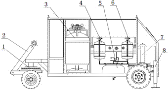
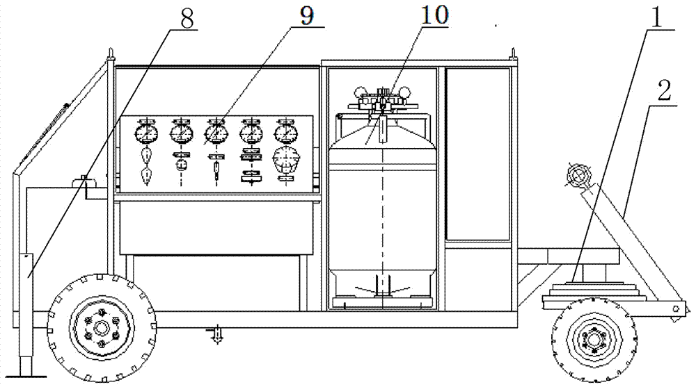
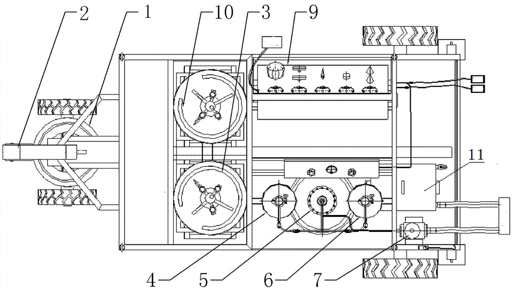
The invention discloses movable nitrogen and liquid filling equipment, and belongs to the field of aviation mechanical equipment. The movable nitrogen and liquid filling equipment comprises a transfer trolley, and a draw bar is arranged at one end of the transfer trolley. A liquid nitrogen tank, a first solution tank, a second solution tank, a mixed liquid tank, a pressure increasing valve and a nitrogen filling tank are arranged on the transfer trolley. The liquid nitrogen tank comprises an inner shell and an outer shell, a vacuum sandwich layer is arranged between the inner shell and the outer shell, and the first solution tank and the second solution tank are each provided with a drain valve and communicate with the mixed liquid tank. Hand valves are arranged at the positions, communicating with the mixed liquid tank, of the first solution tank and the second solution tank. The mixed liquid tank and the nitrogen filling tank are connected with the pressure increasing valve. The nitrogen filling tank is provided with a gas input port and a gas output port. By means of the scheme, the movable nitrogen and liquid filling equipment can widely meet the on-site requirements of large machines such as an airplane for liquid nitrogen, high-pressure nitrogen and cooling liquid, and inconvenience of daily maintenance caused by geographic positions of nitrogen stations is effectively avoided.
Description
technical field [0001] The invention relates to the field of aviation mechanical equipment, in particular to a mobile nitrogen filling and liquid filling equipment. Background technique [0002] With the continuous development of the current aircraft, the electronic equipment in its structure is gradually increasing. When the aircraft is operating on the ground, the heat generated by the electronic equipment is usually high. Therefore, in order to ensure the normal operation of the electronic equipment, the cooling of the electronic equipment needs to be solved. attention. [0003] At present, the electronic systems equipped with various types of aircraft need to be cooled and filled with nitrogen during routine maintenance on the ground. The way of cooling is to use coolant to cool down, but the nitrogen filling is mainly to prevent the oxygen in the atmosphere from chemically reacting with the volatile gases emitted from the electronic equipment of the aircraft and cause ...
Claims
Login to View More Application Information
Patent Timeline
 IPC IPC(8): F17C7/00F17C13/00
CPCF17C7/00F17C13/00F17C2265/06F17C2270/0178
Inventor陈红彦徐玮王自刚李云平
Owner中国航发贵州航空发动机维修有限责任公司