Method for testing pump absorption coefficients of double-coated gain fiber

A technology for gaining optical fiber and absorption coefficient, which is applied in the direction of testing optical fiber/optical waveguide equipment, testing optical performance, etc. It can solve problems such as cumbersome steps, large absorption coefficient measurement value, and potential safety hazards, and achieve high reliability and environmental protection. small effect

Active Publication Date: 2017-10-10
EZHOU INST OF IND TECH HUAZHONG UNIV OF SCI & TECH +1
View PDF5 Cites 11 Cited by
  • Summary
  • Abstract
  • Description
  • Claims
  • Application Information

AI Technical Summary

Problems solved by technology

The disadvantages of this method are: the steps of adjusting the full numerical aperture injection are too cumbersome, and the spatial optical path makes the test structure not stable enough
The disadvantages of this method are: 1. The ASE spectrum is very wide and has a certain intensity. The dichroic film cannot guarantee 100% high transparency to ASE light, so the measured absorption coefficient is likely to be too small
2. It is biased to use the output at 1 cm behind the doped fiber as the total pump light coupled into the fiber, because the fiber absorbs a lot in a short distance from the pump end face, which may cause the measured value of the absorption coefficient to be biased. Big
3. In the process of continuous truncation, there is a possibility of self-excitation. This scheme uses a two-color chip to e...

Method used


Image

  • Method for testing pump absorption coefficients of double-coated gain fiber
  • Method for testing pump absorption coefficients of double-coated gain fiber
  • Method for testing pump absorption coefficients of double-coated gain fiber

Examples


Embodiment Construction

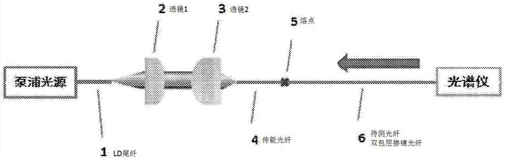
[0038] Such as Figure 4 As shown, the embodiment of the present invention provides a method for testing the absorption coefficient of a double-cladding gain fiber pump, which includes the following steps:

[0039] S1. Using the LD pump light source with the wavelength to be measured in the order of hundreds of watts, the LD pump light source pigtail is fused with the fiber combiner pump pigtail, and the pump light is coupled to the high reflection grating through the fiber combiner. High-reverse grating pigtail output; put the optical power meter on the end of the high-reverse grating output pigtail, adjust the pump light source output power to gradually increase, read the power meter and record a set of power values, denoted as P 1 ;

[0040] S2, select the length as L 0 One end of the double-clad gain fiber to be tested is fused with the high-reflection grating output pigtail, and the other end is cut flat to form an optical resonant cavity;

[0041] S3. Adjust the output power o...


PUM


Abstract

The invention provides a method for testing pump absorption coefficients of a double-coated gain fiber. The method comprises the following steps: (S1) welding an LD pump light source tail fiber with a fiber combiner pump tail fiber by virtue of a hectowatt-order LD pump light source needing to be subjected to wavelength testing, coupling pump light into high reflection grating by virtue of a fiber combiner, outputting the pump light from a high reflection grating tail fiber, and recording an output power value as pump coupling power; (S2) selecting a to-be-tested double-coated gain fiber with an initial length L0 less than or equal to 40m, and building a hectowatt-order vibration structure fiber laser device; (S3) recording power values of a fiber output end by virtue of a truncation method when the lengths of the to-be-tested fiber are L0, L1......LN and power values of an input end when a 45-degree dichroic mirror is inserted into the input end, so as to obtain corresponding surplus pump light power under each fiber length; and (S4) carrying out calculation and statistics so as to obtain the pump absorption coefficients of the double-coated gain fiber. According to the method, the influence caused by ASE upon a testing result can be omitted, a testing platform is stable and safe, and the accurate measurement of the pump absorption coefficients of a double-coated gain fiber is realized.

Description

Technical field [0001] The invention relates to the technical field of fiber lasers, in particular to a method for testing the absorption coefficient of a double-clad gain fiber pump. Background technique [0002] Most of the existing test methods use a low-power pump light source to directly couple into the double-clad gain fiber, and use the physical mechanism that "the gain fiber absorbs the pump light will generate spontaneous radiation, and the pump light output is not completely absorbed". Obtain the remaining pump light, calculate the absorption coefficient, and select a more reasonable value as the effective pump absorption coefficient of the fiber under test by repeatedly cutting and repeating the test. [0003] Existing technology 1 (CN105222998B. National University of Defense Technology 2015) This method injects a broadband light source into the fiber under test with full numerical aperture through spatial coupling, cuts the fiber under test multiple times, obtains the ...

Claims


Application Information

Patent Timeline
IPC IPC(8): G01M11/02
CPCG01M11/35
Inventor 李进延张芳芳廖雷贺兴龙陈益沙李海清彭景刚
Owner EZHOU INST OF IND TECH HUAZHONG UNIV OF SCI & TECH
Why Eureka
Try Eureka