Method of calculating fatigue life of flexible bearing by utilizing finite element modeling

A flexible bearing and fatigue life technology, applied in calculation, computer-aided design, design optimization/simulation, etc., can solve the problems of no flexible bearing simulation method, long experiment time, low applicability, etc., to shorten the development cycle and analyze quickly , without loss of calculation accuracy

Inactive Publication Date: 2017-10-10
SHANGHAI UNIV
View PDF2 Cites 9 Cited by
  • Summary
  • Abstract
  • Description
  • Claims
  • Application Information

AI Technical Summary

Problems solved by technology

[0005] The fatigue life of existing flexible bearings is generally measured through experiments. This method is costly and takes a long time to test. In addition, the general testing machine has limitations on the type and size of the bearing to be tested, so the applicability is not high.
[0006] However, the existing methods of using simulation to calculate fatigue life all take ordinary bearings as the analysis object. The inner and outer rings of this type of b

Method used


Image

  • Method of calculating fatigue life of flexible bearing by utilizing finite element modeling
  • Method of calculating fatigue life of flexible bearing by utilizing finite element modeling
  • Method of calculating fatigue life of flexible bearing by utilizing finite element modeling

Examples


Embodiment 1

[0035] Embodiment 1: Referring to Figures 1 to 5, the present invention uses finite element modeling to calculate the fatigue life of a flexible bearing, which is characterized in that the operating steps are as follows:

[0036] Step 1): Draw the geometric three-dimensional model of the flexible bearing and the camshaft in the UG software, and save it as bearing.stp format;

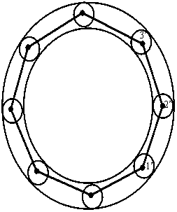
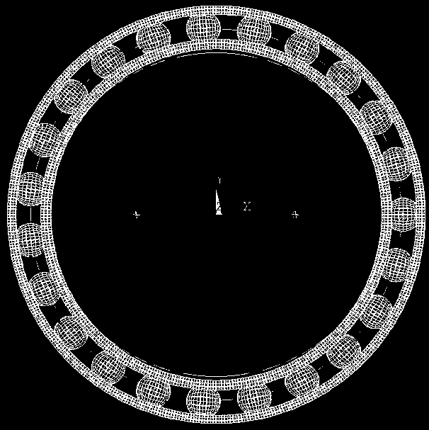
[0037] Step 2): Open the ANSYS software, import the bearing.stp geometric three-dimensional model, divide the inner ring (2), outer ring (3), rolling element (4), and camshaft (1) into hexahedral meshes, and (1)-inner ring (2), inner ring (2)-rolling body (4), outer ring (3)-rolling body (4) set contact relationship;

[0038] Step 3): Add link unit (5) instead of bearing cage;

[0039] Step 4): Apply loads and constraints in the finite element model;

[0040] Step 5): Import the finite element model into the engineering analysis software ANSYS to perform multi-body contact analysis;

[0041] Step 6): ...

Embodiment 2

[0042] Embodiment two: the present embodiment is basically the same as embodiment one, and the features are as follows:

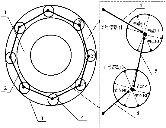
[0043] The specific method of adding the link unit to replace the bearing cage is as follows:

[0044] Step ①: Generate three nodes at the center position of each rolling body. The three nodes generated by No. 1 rolling body can be called 1-1, 1-2, 1-3; the names of the nodes generated by No. 2 rolling body The three nodes are called 2-1, 2-2, 2-3...; the number of flexible bearing rolling elements is 23, so a total of 69 nodes are generated;

[0045] Step ②: Among the nodes generated above, couple the translational degrees of freedom of the nodes at the same position, and the rotational degrees of freedom of the nodes at the same position can be different; the X, The translational degrees of freedom in the Y and Z directions are the same, but the rotational degrees of freedom can be different;

[0046] Step ③: connect the nodes between the adjacent rolli...


PUM


Abstract

The invention discloses a method of calculating the fatigue life of a flexible bearing by utilizing finite element modeling. The method includes: taking the flexible bearing in a harmonic reducer as a research object, establishing a three-dimensional model in UG, establishing a grid model of the flexible bearing in ANSYS software, and simulating, through establishing link units, a cage to realize a constraint effect on rolling elements, wherein a ''link unit-entity'' hybrid finite element model of the flexible bearing is established, and a solid cage model is omitted; and obtaining load distribution under working condition of the flexible bearing according to a finite element analysis result, thus calculating equivalent rolling element loads of the flexible bearing, and then calculating the life of the flexible bearing according to an L-P life theory. Compared with equivalent rolling element loads obtained by empirical formulas, the equivalent rolling element loads obtained by the finite element simulation method utilized in the invention are more accurate. At the same time, the finite element model in the invention is established by adopting a hybrid modeling technology, the calculation scale of the finite element model is reduced, and the calculation time is greatly shortened. The method disclosed in the invention is applicable to different types of flexible bearings, and is low in cost and higher in precision.

Description

technical field [0001] The invention relates to the field of calculation methods for the fatigue life of flexible bearings, in particular to a method for calculating the fatigue life of flexible bearings by using finite element modeling. Background technique [0002] Harmonic gear transmission technology is a new transmission technology produced with the development of aerospace technology in the 1950s. The harmonic reducer is mainly composed of a wave generator, a flexible spline, and a rigid spline. Cam wave generator with flexible bearing is the main wave generator structure used in harmonic drive. [0003] Due to the many unique advantages of harmonic gear transmission, in recent decades, harmonic reducers have been widely used in industrial robots, high-end cars, aerospace, optical instruments, general machinery and other fields. The flexible bearing is a key supporting component of the harmonic reducer, and the fatigue life of the flexible bearing is one of the impor...

Claims


Application Information

Patent Timeline
IPC IPC(8): G06F17/50
CPCG06F30/23G06F2119/04
Inventor 王亚珍姜祎
Owner SHANGHAI UNIV
Why Eureka
Try Eureka