Ball-end milling cutter chatter stability domain lobe graph modeling method based on precise integration in five-shaft numerical control machine tool machining

A ball-end milling cutter and CNC machine tool technology, applied in the direction of electrical digital data processing, special data processing applications, instruments, etc., can solve problems such as difficult errors, and achieve the effect of overcoming calculation accuracy

Active Publication Date: 2017-10-10
DALIAN UNIV OF TECH
View PDF3 Cites 10 Cited by
  • Summary
  • Abstract
  • Description
  • Claims
  • Application Information

AI Technical Summary

Problems solved by technology

However, whether it is the Runge-Kutta method, the full discrete method, or the improved full discrete method, they all belong to the differential classification method in essence. Their advantage is that they are easy to implement, but it is difficult to fundamentally eliminate the error caused by the difference.

Method used


Image

  • Ball-end milling cutter chatter stability domain lobe graph modeling method based on precise integration in five-shaft numerical control machine tool machining
  • Ball-end milling cutter chatter stability domain lobe graph modeling method based on precise integration in five-shaft numerical control machine tool machining
  • Ball-end milling cutter chatter stability domain lobe graph modeling method based on precise integration in five-shaft numerical control machine tool machining

Examples


Embodiment Construction

[0046] The specific embodiments of the present invention will be described in detail below in conjunction with the technical solutions and accompanying drawings.

[0047] A method for modeling lobe diagrams in the chatter stability domain of ball-end milling cutters based on fine integration in machining on a five-axis CNC machine tool, including the following steps:

[0048] Step 1: Establish the ball end milling cutter tool-workpiece dynamics equation

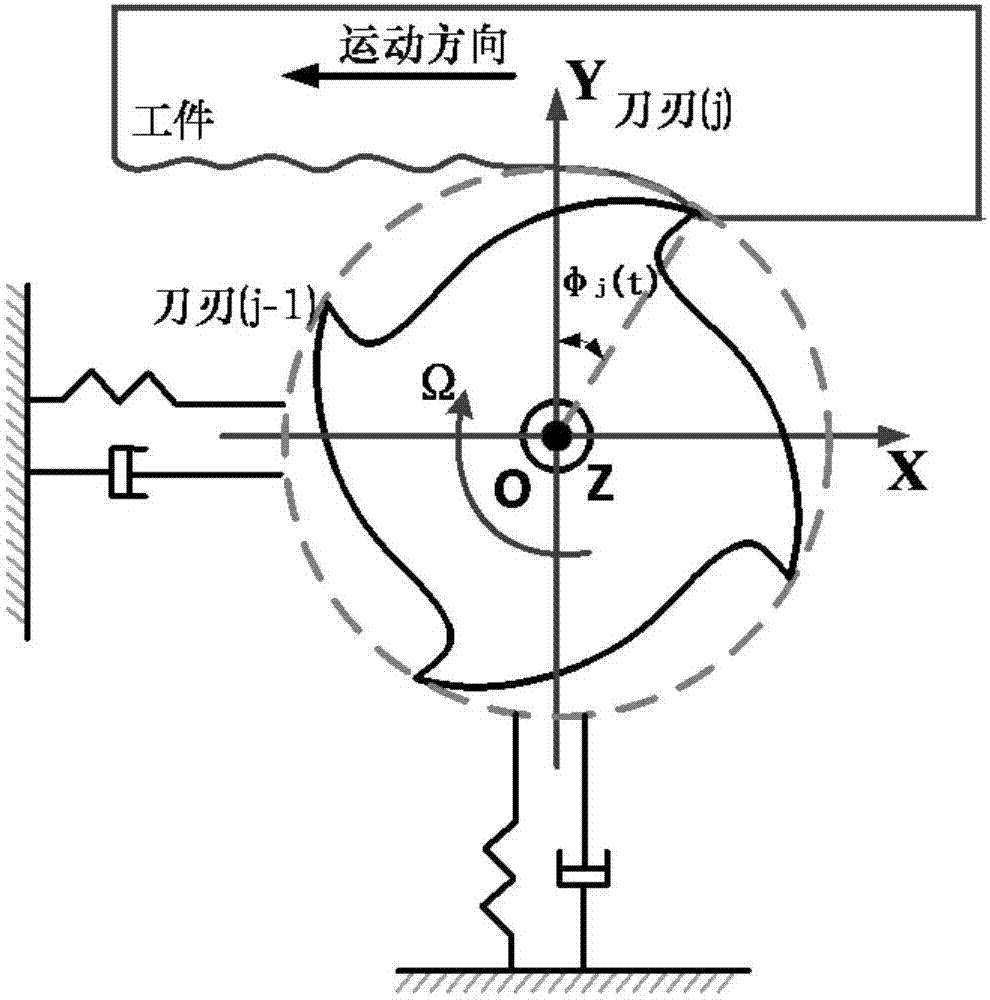
[0049] The tool-workpiece system of ball nose milling cutter is simplified as image 3 The two-degree-of-freedom system shown only considers the tool vibration factors in the feed direction x and normal y direction, and establishes the dynamic equation as shown below:

[0050]

[0051] Among them, m tx , ξ x , ω nx are the modal mass, damping coefficient, and natural frequency of the tool system in the x direction; m ty , ξ y , ω ny are the modal mass, damping coefficient, and natural frequency of the tool system in t...


PUM


Abstract

The invention provides a ball-end milling cutter chatter stability domain lobe graph modeling method based on a precise integration in five-shaft numerical control machine tool machining, and belongs to the technical field of advanced manufacturing. The method comprises the steps of 1, establishing a ball-end milling cutter-workpiece kinetic equation; 2, solving dynamic cutting forces Ftx(t) and Fty(t) on ball-end milling cutter teeth; 3; conducting semi-analytic modeling on a contact area of a ball-end milling cutter and a workpiece in the five-shaft numerical control machine tool plane machining process; 4, using a precise integration method to solve a cutter-workpiece kinetic equation time-domain numerical value; 5, constructing a lobe graph. In the ball-end milling cutter chatter stability domain lobe graph modeling method based on the precise integration in five-shaft numerical control machine tool machining, the ball-end milling cutter is used as arc motion in a single-tooth cutting cycle, the precise integration method is utilized to conduct high-precision time-domain numerical value solving on a cutting system second order kinetic equation, the disadvantage of a traditional numerical value solving method that the calculation precision, the calculation efficiency and the stability cannot be considered simultaneously is overcome, and the ball-end milling cutter chatter stability time-domain lobe graph when a front rake angle and a back rake angle exist in the five-shaft numerical control machine tool machining process can be constructed.

Description

technical field [0001] The invention belongs to the technical field of mechanical manufacturing, and relates to a method for modeling a flutter stable domain in the milling and cutting process of a five-axis numerical control machine tool, in particular to modeling a lobe diagram of a chatter stable domain in the milling and cutting process of a ball-end milling cutter in a five-axis numerical control machine tool method. Background technique [0002] As the pillar of national economic growth, the machinery manufacturing industry has developed for hundreds of years. It has established a relatively systematic theoretical system and accumulated rich practical experience. direction development. [0003] High-speed milling is one of the most important basic technologies in advanced manufacturing technology. It is the most important and widely used processing method at present. However, cutting chatter caused by inappropriate cutting parameters in the high-speed milling process ...

Claims


Application Information

Patent Timeline
IPC IPC(8): G06F17/50
CPCG06F30/17
Inventor 李宏坤代月帮
Owner DALIAN UNIV OF TECH
Why Eureka
Try Eureka