
Battery pack with high heat dissipation performance

A battery pack and high heat dissipation technology, applied in secondary batteries, battery temperature control, circuits, etc., can solve the problems of battery pack high temperature fire, battery pack internal structure complex, battery pack temperature rise, etc., to ensure consistency, good Ventilation and cooling effect to ensure rapid effect

Active Publication Date: 2017-10-10
SYST ELECTRONICS TECH ZHENJIANG CO LTD
View PDF5 Cites 4 Cited by
  • Summary
  • Abstract
  • Description
  • Claims
  • Application Information

AI Technical Summary

Problems solved by technology

During the use of the battery pack, a large amount of heat will be generated, causing the temperature of the battery pack to rise. Especially in summer, the battery pack is prone to high-temperature fire, explosion and other safety hazards.
Battery pack heat dissipation technology is a major problem. Battery pack sealing requirements for safety considerations and battery pack heat dissipation are relatively contradictory issues. The battery pack heat dissipation methods used in the prior art mainly include forced air cooling and liquid cooling. The cooling method is to install the fan on the battery pack box, and take away the heat in the battery pack through the wind. The disadvantage of this method is that the local temperature in the battery pack is uneven, and the temperature of the air inlet is often low, while the outlet The temperature around the tuyere is high. This uneven temperature directly affects the consistency of the single cells in the battery pack, which will accelerate the deterioration of the performance of the battery pack, and the airtightness of the battery pack is not good.
In addition, although the liquid cooling method has a better heat dissipation effect, the internal structure of the battery pack is complicated, which will increase the weight and cost of the battery pack

Method used


Image

  • Battery pack with high heat dissipation performance
  • Battery pack with high heat dissipation performance
  • Battery pack with high heat dissipation performance

Examples


Embodiment Construction

[0019] The present invention will be further described below in conjunction with the drawings and specific embodiments.

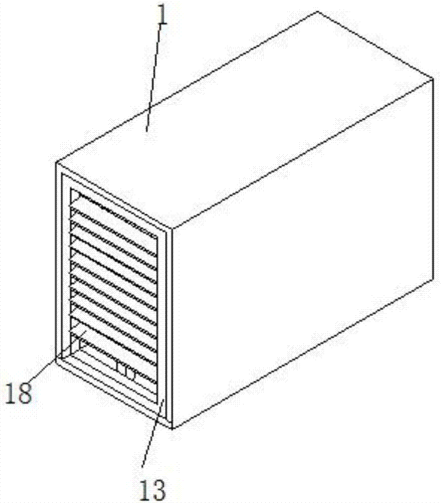
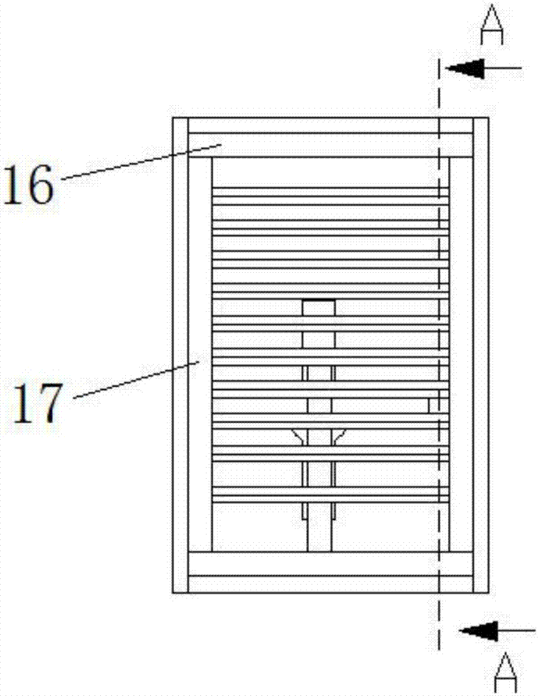
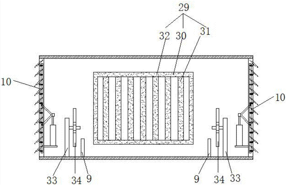
[0020] A battery pack with high heat dissipation performance, including battery components, ventilation devices, liquid cooling devices, and a box body. The box body includes an upper plate, a lower plate and a side plate. The box body is a hollow structure, and the two side plates are placed in mirror image. , The lower plate is located between the two side plates, the upper plate is sealed and connected with the top surfaces of the two side plates, and the lower plate is sealed and connected with the bottom surfaces of the two side plates; both ends of the box body are respectively provided with a ventilation area, two ventilation areas There is a heat dissipation area beside the area, a battery area is set between the two heat dissipation areas, and the heat dissipation area and the battery area are separated by positioning blocks;

[0021] The ventilation de...


PUM


Abstract

The invention provides a battery pack with high heat dissipation performance. A temperature sensor is used for transmitting an internal temperature signal to a programmable logic controller (PLC), a fan is controlled to work by the PCL according to a temperature in the battery pack, and heat of a battery module is taken away by wind; by a ventilation device, the sealing performance and the heat dissipation performance of the battery pack are simultaneously satisfied, and the working of the ventilation device is controlled by a travel switch and the PLC to achieve automation; by arranging a liquid-cooling device, the rapidness of heat dissipation is ensured, the temperature consistency of the battery module in the battery pack is ensured as well as the heat is dissipated; and by dual cooling of the liquid-cooling device and the ventilation device, the battery module can be enabled to obtain a good ventilation and cooling effect.

Description

Technical field [0001] The invention relates to battery heat dissipation technology, in particular to a battery pack with high heat dissipation performance. Background technique [0002] A module is composed of multiple single cells or super capacitors in series and parallel, and then multiple modules are connected in series and parallel to form a battery pack with a certain voltage and capacity, which is placed in a sealed box to form a battery pack. During the use of the battery pack, a lot of heat will be generated, causing the temperature of the battery pack to rise, especially in summer, the battery pack is prone to high-temperature fire, explosion and other safety hazards. Battery pack heat dissipation technology is a big problem. The battery pack sealing requirements and battery pack heat dissipation for safety considerations are relatively contradictory issues. The battery pack heat dissipation methods used in the prior art mainly include forced air cooling and liquid coo...

Claims


Application Information

Patent Timeline
IPC IPC(8): H01M10/613H01M10/637H01M10/63H01M10/6556H01M10/6563H01M10/6568H01G11/18
CPCH01M10/613H01M10/63H01M10/637H01M10/6556H01M10/6563H01M10/6568H01G11/18Y02E60/10
Inventor 任纯麟
Owner SYST ELECTRONICS TECH ZHENJIANG CO LTD
Learn More