Automatic dust collector
The technology of a dust removal device and a dust remover, which is applied in the direction of a combination device, a separation device, a chemical instrument and a method, etc., can solve problems such as failure to achieve energy conservation and environmental protection, poor dust removal effect of a dust removal device, and high noise of a dust removal device, and achieve saving Production cost, elimination of aerodynamic noise, effect of good noise reduction effect
- Summary
- Abstract
- Description
- Claims
- Application Information
AI Technical Summary
Problems solved by technology
Method used
Image
Examples
Embodiment 1
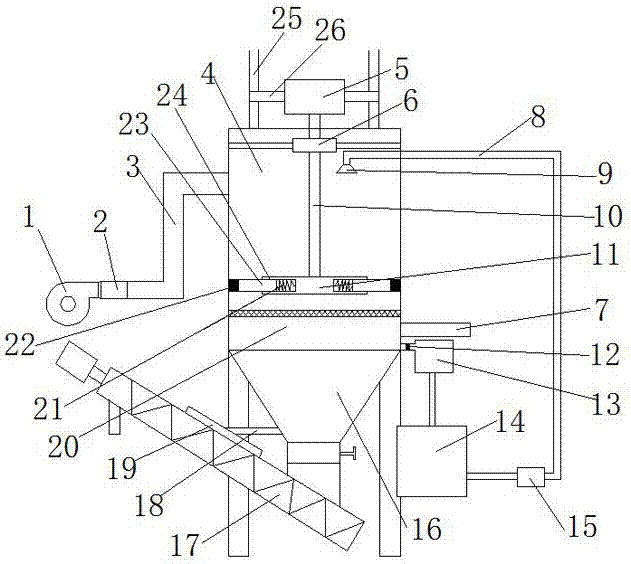
[0024] Such as figure 1 As shown, an automatic dust removal device includes a support frame and a dust remover 4 arranged on the support frame. The top of the dust remover 4 is provided with a water inlet pipe 8, and the end of the water inlet pipe 8 is provided with a nozzle 9. The dust remover 4 is provided with a dust collector Filter screen 20, one side of the dust collector 4 is provided with an air inlet pipe 3 connected to the fan 1, and the other side of the dust collector 4 is provided with an air outlet pipe 7, which also includes an air volume adjustment device, a noise reduction device 2, a water circulation device and a control system, The air volume adjustment device is set on the air inlet pipe 3, the muffler device 2 is connected to the air outlet of the fan 1, the water circulation device is connected to the water inlet pipe 8, the water inlet pipe 8 is provided with a water volume regulating valve, and the dust collector 4 is provided with a dust concentration...
Embodiment 2
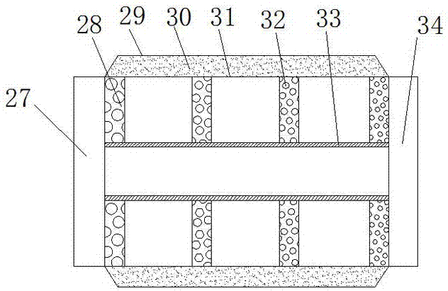
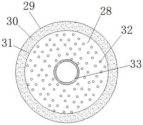
[0033] It differs from Embodiment 1 in that: as figure 2 with image 3 As shown, the four sound-absorbing plates 26 are arranged successively along the air inlet direction, and each sound-absorbing plate 28 is provided with a plurality of sound-absorbing holes 32, and the diameter of the sound-absorbing holes on the latter sound-absorbing plate is smaller than that of the adjacent preceding sound-absorbing plate The diameter of the upper silencing hole, that is, along the air inlet direction, the diameter of the silencing hole on the second silencing plate is smaller than the diameter of the silencing hole on the first silencing plate, and the diameter of the silencing hole on the third silencing plate is smaller than that of the second silencing hole The diameter of the sound-absorbing hole on the plate, the diameter of the sound-absorbing hole on the fourth sound-absorbing plate is smaller than the diameter of the sound-absorbing hole on the third sound-absorbing plate, the...
Embodiment 3
[0035] It differs from Embodiment 1 in that: as figure 1 As shown, the lower end of the sedimentation water tank 16 is provided with an upwardly inclined spiral feed pipe 17, the lower end of the spiral feed pipe 17 is connected to the lower end of the sedimentation water tank 16, and the spiral feed pipe 17 is provided on the pipe wall facing the sedimentation water tank 16. There is a water-distributing channel 19 protruding outward, and the water-distributing channel 19 communicates with the sedimentation water tank 16 through the return water channel 18 .
[0036] The dust settled at the bottom of the sedimentation water tank 16 is discharged from the bottom of the sedimentation water tank 16 into the screw delivery pipe 17, and part of the water will be discharged while the dust is discharged. Only dust is discharged, and water is not discharged. The water enters the water diversion channel 19, and then is diverted to the sedimentation water tank 16 through the return wat...
PUM
 Abstract
Description
Claims
Application Information
 - R&D
- Intellectual Property
- Life Sciences
- Materials
- Tech Scout
- Unparalleled Data Quality
- Higher Quality Content
- 60% Fewer Hallucinations
Browse by: Latest US Patents, China's latest patents, Technical Efficacy Thesaurus, Application Domain, Technology Topic, Popular Technical Reports.
© 2025 PatSnap. All rights reserved.Legal|Privacy policy|Modern Slavery Act Transparency Statement|Sitemap|About US| Contact US: help@patsnap.com


