An automatic dust removal device

A technology for a dust removal device and a dust collector, which is applied to separation devices, combined devices, chemical instruments and methods, etc., can solve the problems of not being able to achieve energy saving and environmental protection well, the dust removal effect of the dust removal device is not good, and the dust removal device is noisy, etc. Production cost, elimination of aerodynamic noise, and the effect of good noise reduction

Active Publication Date: 2019-05-24
HENAN POLYTECHNIC
View PDF6 Cites 0 Cited by
  • Summary
  • Abstract
  • Description
  • Claims
  • Application Information

AI Technical Summary

Problems solved by technology

[0005] In view of this, the purpose of the present invention is to provide an automatic dust removal device for the deficiencies in the prior art, which solves the problems of poor dust removal effect, low degree of automation, large noise generated by the dust removal device, and the inability to achieve Energy saving and environmental protection issues

Method used


Image

  • An automatic dust removal device
  • An automatic dust removal device
  • An automatic dust removal device

Examples


Embodiment 1

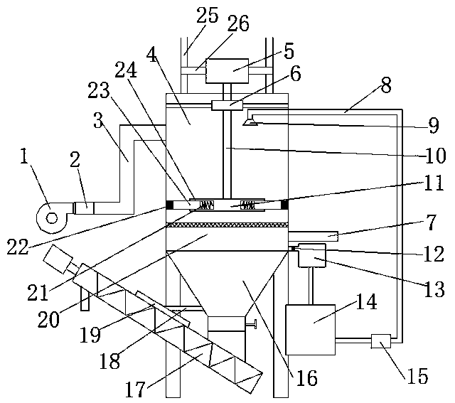
[0024] Such as figure 1 As shown, an automatic dust removal device includes a support frame and a dust remover 4 arranged on the support frame. The top of the dust remover 4 is provided with a water inlet pipe 8, and the end of the water inlet pipe 8 is provided with a nozzle 9. The dust remover 4 is provided with a dust collector Filter screen 20, one side of the dust collector 4 is provided with an air inlet pipe 3 connected to the fan 1, and the other side of the dust collector 4 is provided with an air outlet pipe 7, which also includes an air volume adjustment device, a noise reduction device 2, a water circulation device and a control system, The air volume adjustment device is set on the air inlet pipe 3, the muffler device 2 is connected to the air outlet of the fan 1, the water circulation device is connected to the water inlet pipe 8, the water inlet pipe 8 is provided with a water volume regulating valve, and the dust collector 4 is provided with a dust concentration...

Embodiment 2

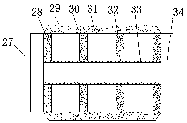
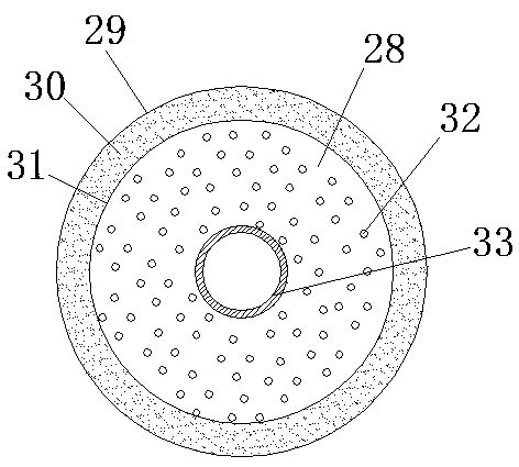
[0033] It differs from Embodiment 1 in that: as figure 2 and image 3 As shown, the four sound-absorbing plates 26 are arranged successively along the air inlet direction, and each sound-absorbing plate 28 is provided with a plurality of sound-absorbing holes 32, and the diameter of the sound-absorbing holes on the latter sound-absorbing plate is smaller than that of the adjacent preceding sound-absorbing plate The diameter of the upper silencing hole, that is, along the air inlet direction, the diameter of the silencing hole on the second silencing plate is smaller than the diameter of the silencing hole on the first silencing plate, and the diameter of the silencing hole on the third silencing plate is smaller than that of the second silencing hole The diameter of the sound-absorbing hole on the plate, the diameter of the sound-absorbing hole on the fourth sound-absorbing plate is smaller than the diameter of the sound-absorbing hole on the third sound-absorbing plate, ther...

Embodiment 3

[0035] It differs from Embodiment 1 in that: as figure 1 As shown, the lower end of the sedimentation water tank 16 is provided with an upwardly inclined spiral feed pipe 17, the lower end of the spiral feed pipe 17 is connected to the lower end of the sedimentation water tank 16, and the spiral feed pipe 17 is provided on the pipe wall facing the sedimentation water tank 16. There is a water-distributing channel 19 protruding outward, and the water-distributing channel 19 communicates with the sedimentation water tank 16 through the return water channel 18 .

[0036] The dust settled at the bottom of the sedimentation water tank 16 is discharged from the bottom of the sedimentation water tank 16 into the screw delivery pipe 17, and part of the water will be discharged while the dust is discharged. Only dust is discharged, and water is not discharged. The water enters the water diversion channel 19, and then is diverted to the sedimentation water tank 16 through the return wat...


PUM


Abstract

The invention discloses an automatic dedusting device, which belongs to the technical field of dedusting devices and comprises a support frame and a dust remover arranged on the support frame. Dust removal filter, one side of the dust collector is provided with an air inlet pipe connected to the fan, and the other side of the dust collector is provided with an air outlet pipe, which also includes an air volume adjustment device, a noise reduction device, a water circulation device and a control system. The air volume adjustment device is located at the inlet On the air duct, the muffler is connected to the air outlet of the fan, the water circulation device is connected to the water inlet pipe, the water flow regulating valve is installed on the water inlet pipe, the dust concentration sensor is installed in the dust collector, and the control system is respectively connected with the air flow regulating device, water regulating valve, Dust concentration sensor connection. The invention can achieve good automatic dust removal effect, realize good noise reduction effect, and achieve the effect of energy saving and environmental protection.

Description

technical field [0001] The invention belongs to the technical field of dust removal devices, and in particular relates to an automatic dust removal device. Background technique [0002] The dust removal device is a device used to remove or reduce the content of flying dust in the flue gas. It is used in the production workshop of factories and enterprises to purify the dust in the air and achieve the goal of environmental protection and health. The types of dust removal devices can be divided into bionano film dust suppression devices, cloud and fog dust suppression devices, bag dust removal devices, cyclone dust removal devices, wet dust removal devices, electrostatic dust removal devices, desulfurization and dust removal devices, etc. However, the dust removal effect of current dust removal devices is poor. The degree of automation is low, the noise generated by the dust removal device is large, and the effect of energy saving and environmental protection cannot be well ac...

Claims


Application Information

Patent Timeline
Patent Type & Authority Patents(China)
IPC IPC(8): B01D50/00B01D47/06B01D36/04
CPCB01D36/04B01D47/06B01D2247/08B01D2247/04B01D50/60
Inventor 陈辉王蕊张柯
Owner HENAN POLYTECHNIC
Why Eureka
Try Eureka