Desulfurization tower

A desulfurization tower and tower body technology, which is applied in the field of air pollution control in the environmental protection industry, can solve the problem of low sulfur dioxide removal rate

Active Publication Date: 2017-10-13
CHENGDU GUOHUA ENVIRONMENTAL TECH
View PDF12 Cites 1 Cited by
  • Summary
  • Abstract
  • Description
  • Claims
  • Application Information

AI Technical Summary

Problems solved by technology

[0007] The purpose of this application is to provide a desulfurization equipment that can improve the sulfur dioxide removal rate in view of the problem that the sulfur dioxide removal rate in the current desulfurization equipment line is not high

Method used


Image

  • Desulfurization tower
  • Desulfurization tower
  • Desulfurization tower

Examples


Embodiment 1

[0163] Example 1, such as Figure 1-13 Shown:

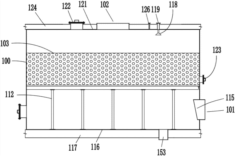
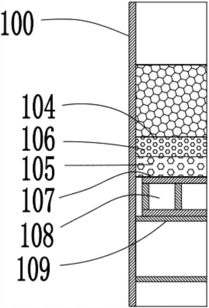
[0164] A filter layer assembly for a desulfurization tower. The filter layer assembly 103 is located between the flue gas inlet 101 and the flue gas outlet 102 of the desulfurization tower, so that the flue gas passes through the filter layer assembly 103 first, and then the flue gas The air outlet 102 is discharged. The filter layer assembly 103 includes a filter layer 132, and a plurality of flue gas passages for the flue gas to pass through the filter layer 132.

[0165] In the filter layer assembly 103 of the present application, in the filter layer 132 there are a number of channels for the flue gas to pass through. The flue gas entering the tower body 100 passes through these channels and then is discharged from the flue gas outlet 102. In this way, the flue gas can be greatly improved. The contact efficiency of the sulfur dioxide and the desulfurizing agent in the flue gas is further improved. The desulfurizing agent in this a...

Embodiment 2

[0187] Example 2, such as Figure 1-13 Shown:

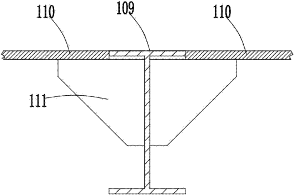
[0188] A catalyst support assembly for a desulfurization tower, the support assembly is arranged in the tower body 100 of the desulfurization tower, the support assembly is located below the filter layer assembly 103, and the support assembly is used to support the filter layer assembly 103. Separate the filter layer assembly 103 from the bottom of the tower body 100.

[0189] In this solution, the filter layer assembly 103 is separated from the bottom of the tower body 100 by supporting components. On the one hand, it is convenient for the flue gas to have enough space to fill the space below the filter layer assembly 103, and to prevent the smoke from only entering the smoke from close to The filter layer of the mouth part passes through, thereby ensuring the filtration efficiency of the sulfur dioxide of the filter layer.

[0190] Preferably, the supporting assembly includes a grid plate 108, the edge of the grid plate 108 is match...

Embodiment 3

[0207] Example 3, such as Figure 1-13 Shown:

[0208] The application also discloses a tower body for desulfurization tower,

[0209] A smoke inlet pipe 115 is connected to the flue gas inlet 101, one end of the smoke inlet pipe 115 extends into the tower body 100, and in the vertical direction, the smoke inlet pipe 115 located inside the tower body 100, There are occlusions above any part of the inner wall.

[0210] In this solution, there is a shelter above any part of the inner wall of the tower body 100, so as to prevent the liquid or other materials above from falling into the flue gas pipe 115 and affecting the flue gas transportation. In the solution of this method, the vertical In the straight direction, the smoke inlet pipe 115 located inside the tower body 100 has a shield above any part of its inner wall. The shield can be arranged to incline the smoke inlet pipe 115 so that the port of the smoke inlet pipe 115 is inclined. , So that the upper part of the port forms th...


PUM

PropertyMeasurementUnit
diameteraaaaaaaaaa

Abstract

The invention relates to the technical field of atmospheric pollution treatment in an environmental protection industry and in particular relates to a desulfurization tower. The desulfurization tower comprises a filtering layer assembly, wherein the filtering layer assembly is located between a flue gas inlet and a flue gas outlet of the desulfurization tower; after flue gas firstly passes through the filtering layer assembly, the flue gas is exhausted from the flue gas outlet; the filtering layer assembly comprises a filtering layer; the filtering layer is internally provided with a plurality of flue gas channels through which the flue gas passes. According to the desulfurization tower provided by the invention, the contact efficiency of sulfur dioxide and a desulfurization agent in the flue gas can be greatly improved, so that the removal efficiency of the sulfur dioxide in the flue gas is improved; the desulfurization agent can be a chemical preparation which can be subjected to chemical reaction with the sulfur dioxide so as to remove the sulfur dioxide and can also be a catalyst which is used for catalyzing the sulfur dioxide to be subjected to chemical reaction with other substances so as to remove the sulfur dioxide.

Description

Technical field [0001] This application relates to the technical field of air pollution control in the environmental protection industry, and specifically relates to a desulfurization tower. Background technique [0002] Sulfur dioxide and others are the main pollutants in the atmosphere, which are very harmful to the links and human health, and are also the main cause of acid rain. With the rapid economic development, my country's sulfur dioxide emissions have ranked first in the world, and acid rain has appeared to varying degrees in various places, which has become a heavily polluted area after Europe and North America. Therefore, the removal and treatment of sulfur dioxide in industrial flue gas is an important topic in the field of environmental protection in my country. [0003] For the sulfur dioxide removal treatment of industrial flue gas, the usual way is to use a desulfurization equipment line to treat the sulfur dioxide in the industrial flue gas. The current desulfur...

Claims


Application Information

Patent Timeline
Patent Type & Authority Applications(China)
IPC IPC(8): B01D53/50B01D53/86B01D53/88B01D53/96B01D53/82
CPCB01D53/8609B01D53/885B01D53/96B01D2258/06B01D2259/128B01D2251/60Y02A50/20
Inventor 麻强王维江王怀金李立松荀鹏王平朱伟余永红
Owner CHENGDU GUOHUA ENVIRONMENTAL TECH
Why Eureka
Try Eureka