Pneumatic tire
A technology for pneumatic tires and sidewalls, applied to tire parts, tire edges, transportation and packaging, etc., can solve the risk of increasing the separation of curtain yarn and rubber material, increase the fluidity of rubber material in the bead part, and increase the rigidity of the sidewall part Insufficient and other problems, to achieve the effect of reducing the risk of separation, reducing damage, and improving rigidity
- Summary
- Abstract
- Description
- Claims
- Application Information
AI Technical Summary
Problems solved by technology
Method used
Image
Examples
Embodiment 1
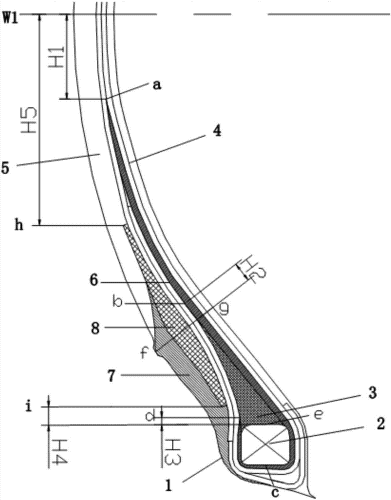
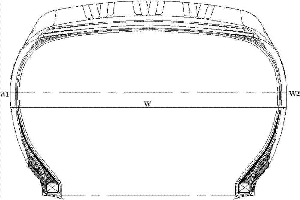
[0058] The structure of the pneumatic tire provided by this embodiment is as follows: Figure 2~3 As shown, the tire comprises two bead portions 1, two bead cores 2, two sidewalls 5, a crown and two carcass plies 4; said carcass plies pass from the bead portions through the sidewalls Extending to the crown; each bead portion 1 has a bead filler 3; each sidewall portion 1 is provided with a bead protective rubber 7 axially outward;
[0059] A first reinforcing rubber sheet 6 is arranged between the carcass ply 4 and the bead filler 3 in the axial direction. The radial upper end a extends downward along the middle of the two layers of ply, reaches the radial top b of the bead filler, and extends from the inner side of the bead filler axially to the lower side, bypassing the lower edge c of the bead core, Then wrap up until the lower end d; the distance H1 between the radial upper end a of the first reinforcing film 6 and W1 is 10 mm; the radial height of the bead filler 3 on th...
Embodiment 2
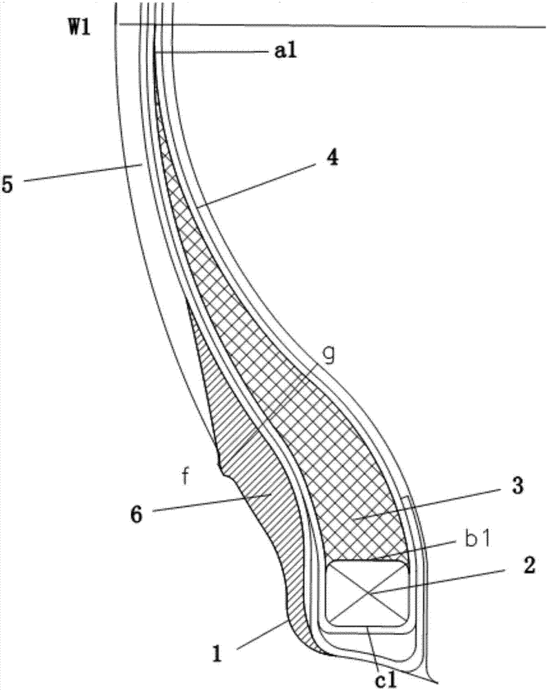
[0065]The present invention selects the pneumatic tire described in Example 1 of the 175 / 70R14C specification, and carries out the indoor durability running test. With embodiment 1 tire (choose 5 tires) and comparative tire (choose 2, its size, composition are all identical with embodiment 1, structure such as figure 1 Shown) are respectively installed on the same standard rim, filled with a pressure of 375kPa and a load of 518kg, driven by the tire test drum to rotate at a speed of 81 km / h at an ambient temperature of 38°C, and the load is increased to the load of the ETRTO 2017 regulation Stabilize after 160%, stop running until the tire is damaged, and record the mileage of the tire.
[0066] The test results are shown in Table 1, and the test results are represented by an index, the index takes the comparative tire 1 as a reference value of 100, and the larger the index, the better the result. It can be seen from Table 1 that the tires of the embodiments of the present in...
Embodiment 3
[0071] The structure of the pneumatic tire provided by this embodiment is as follows: Figure 2~3 As shown, the tire comprises two bead portions 1, two bead cores 2, two sidewalls 5, a crown and two carcass plies 4; said carcass plies pass from the bead portions through the sidewalls Extending to the crown; each bead portion 1 has a bead filler 3; each sidewall portion 1 is provided with a bead protective rubber 7 axially outward;
[0072] A first reinforcing rubber sheet 6 is arranged between the carcass ply 4 and the bead filler 3 in the axial direction. The radial upper end a extends downward along the middle of the two layers of ply, reaches the radial top b of the bead filler, and extends from the inner side of the bead filler axially to the lower side, bypassing the lower edge c of the bead core, Then wrap up until the lower end d; the distance H1 between the radially upper end a of the first reinforcing film 6 and W1 is 12mm; the radial distance of the bead filler 3 at...
PUM
| Property | Measurement | Unit |
|---|---|---|
| thickness | aaaaa | aaaaa |
| hardness | aaaaa | aaaaa |
| hardness | aaaaa | aaaaa |
Abstract
Description
Claims
Application Information
 - R&D
- Intellectual Property
- Life Sciences
- Materials
- Tech Scout
- Unparalleled Data Quality
- Higher Quality Content
- 60% Fewer Hallucinations
Browse by: Latest US Patents, China's latest patents, Technical Efficacy Thesaurus, Application Domain, Technology Topic, Popular Technical Reports.
© 2025 PatSnap. All rights reserved.Legal|Privacy policy|Modern Slavery Act Transparency Statement|Sitemap|About US| Contact US: help@patsnap.com


