Vertical shaft wall structure in bad stratum and construction device and method

A wall structure, poor technology, applied in shaft equipment, borehole/well components, sinking, etc., can solve the problems of layered backfill homogeneous soil, long construction period, difficult large-scale excavation, high cost, etc.

Active Publication Date: 2017-10-13
MAGANG (GROUP) HOLDING CO LTD
View PDF10 Cites 20 Cited by
  • Summary
  • Abstract
  • Description
  • Claims
  • Application Information

AI Technical Summary

Problems solved by technology

The soil replacement method is used to strengthen the structure. First, the thick water-containing backfill topsoil layer is completely excavated, the well wall structure is poured, and then the homogeneous soil is backfilled layer by layer. The disadvantages are: the surface excavation area is large, and it is difficult to Difficult to excavate in a large area; layered backfill with homogeneous soil has a long construction period and high cost
The freezing method strengthens the structure by drilling one or two circles of freezing holes from the surface to the bottom of the stable rock formation or wellbore for 10m to 20m, setting up frozen steel pipes in the entire hole in the freezing holes, and arranging a freezing station on the surface to circulate the refrigerant through the frozen steel pipes. It is transported to the bottom of the freezing hole, so as to reach the surrounding rock around the freezing shaft, so as to achieve the purpose of preventing seepage and strengthening the surrou

Method used


Image

  • Vertical shaft wall structure in bad stratum and construction device and method
  • Vertical shaft wall structure in bad stratum and construction device and method
  • Vertical shaft wall structure in bad stratum and construction device and method

Examples


Embodiment Construction

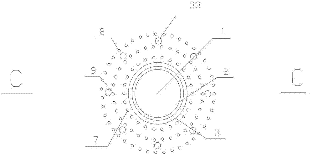
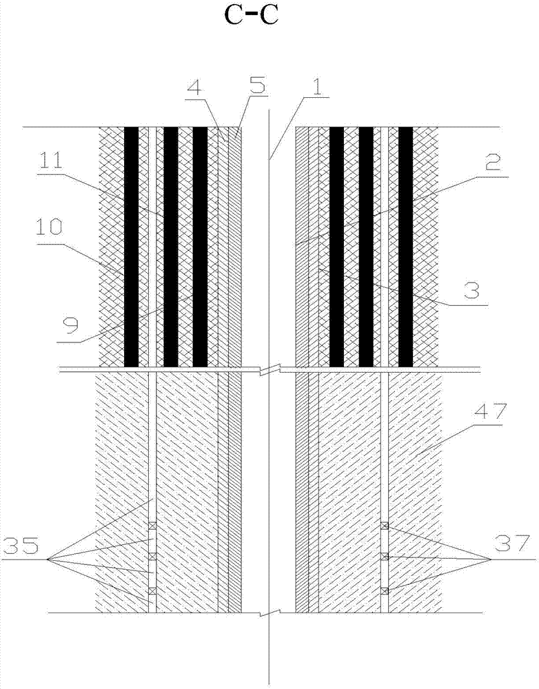
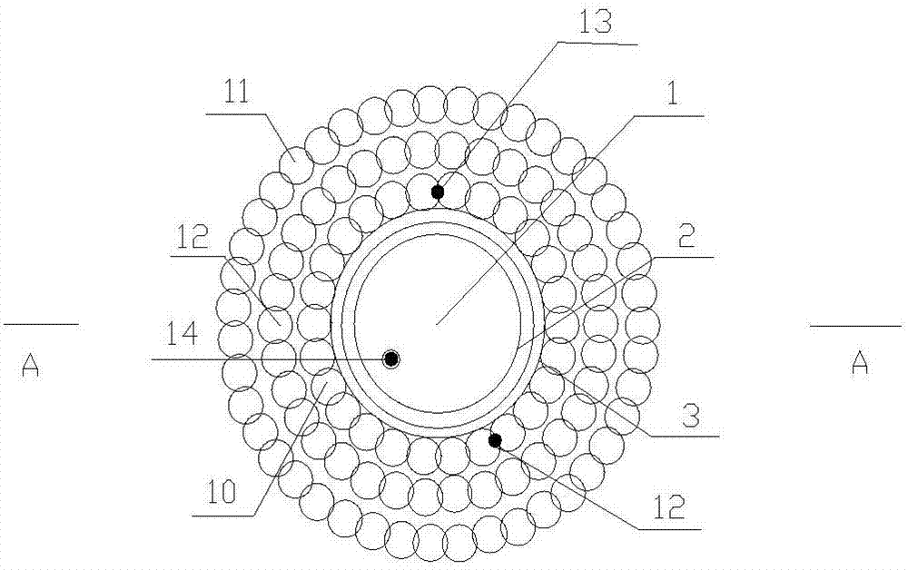
[0068] Depend on figure 1 , figure 2 , Figure 5 , Figure 6 , Figure 9It can be seen from the figure that a shaft wall structure in unfavorable formations includes the wellbore set in unfavorable formations, the wall structure of the high-spray curtain pile set in the neck section of the upper part of the shaft, and the positioning and targeting set in the bedrock section. The grouting well wall structure and the well wall, the upper and lower well walls are concentric and have the same diameter, and are closely connected into one; the well wall structure of the high-spray curtain pile at the neck section of the vertical well, the rock formation is excavated in the barren diameter line 3 of the wellbore, and the wellbore The shaft wall shall be poured between the clear diameter line 2 and the poor diameter line of the shaft, with the center of the shaft 1.1 as the center (not marked in the figure), and at least three ring-shaped high-spray curtain walls closed at the end...


PUM

PropertyMeasurementUnit
Drilling diameteraaaaaaaaaa
Diameteraaaaaaaaaa
Diameteraaaaaaaaaa

Abstract

The invention relates to a vertical shaft wall structure in a bad stratum and belongs to mine vertical shaft construction. The vertical shaft wall structure comprises a shaft arranged in the bad stratum and is characterized in that the upper shaft collar section of a vertical shaft is provided with a high-pressure-jet-grouting curtain pile shaft wall structure, a bedrock section is provided with a positioning targeting grouting section shaft wall structure and a shaft wall, and the upper and lower shaft wall structures are concentric, identical in diameter and tightly integrally connected to protect the shaft wall; the high-pressure-jet-grouting curtain pile shaft wall structure is provided with at least three circles of annular high-pressure-jet-grouting curtain walls with sealed heads and tails on the periphery, 0.6m away from a shaft outer diameter line, of the shaft outer diameter line by using the center of the shaft as the circle center, the positioning targeting grouting section shaft wall structure is provided with at least 8 positioning targeting grouting sections, vertical to the ground, on the periphery, 2m away from the shaft outer diameter line, of the shaft outer diameter line, and the two wall structures protect the shaft wall. The vertical shaft wall structure has the advantages that the vertical shaft wall structure is novel in concept, simple, stable and reliable; the high-pressure-jet-grouting curtain walls and the positioning targeting grouting sections protect the shaft wall, bearing capacity and deformation resistance are enhanced, and a good water blocking effect is achieved; the vertical shaft wall structure is fast and convenient in construction, fast shaft construction can be achieved, cost can be saved, and mine production can be performed safely and smoothly.

Description

Technical field: [0001] The invention belongs to mine vertical shaft construction, and in particular relates to shaft wall structures and construction methods in unfavorable formations. Background technique [0002] In underground mining, the vertical shaft is an important passage for lifting, ventilation, transportation, drainage and personnel safety connecting the underground and the surface. The shaft is directly connected to the surface and directly bears all the loads of the shaft lifting facilities. Therefore, it is necessary to ensure that the shaft shaft structure has sufficient bearing capacity. strength and resistance to deformation. The vertical wellbore is from top to bottom: the well neck, the well body and the bottom of the well. With the rapid development of the global mining industry, the proportion of underground mining is increasing, the shafts are getting deeper and the formations they pass through are becoming more and more complex. The unfavorable form...

Claims


Application Information

Patent Timeline
IPC IPC(8): E21D5/00E21D5/04E21D5/11E21D5/12E21D1/10E21B7/04E21B33/13
CPCE21B7/04E21B33/13E21D1/10E21D5/00E21D5/04E21D5/11E21D5/12Y02E10/20
Inventor 董亚宁
Owner MAGANG (GROUP) HOLDING CO LTD
Why Eureka
Try Eureka