
A combined axicon device

An axicon and combined technology, applied in the laser field, can solve the problems of increasing processing cost, increasing the difficulty of component processing, limiting non-diffracting beams, etc., and achieving the effect of reducing processing difficulty and processing cost

Active Publication Date: 2020-05-12
SHANDONG INST OF AEROSPACE ELECTRONICS TECH
View PDF4 Cites 0 Cited by
  • Summary
  • Abstract
  • Description
  • Claims
  • Application Information

AI Technical Summary

Problems solved by technology

However, due to the pyramidal structure of the axicon, the use of it to generate non-diffraction beams is limited by the base angle of the axicon. To produce high-quality, long-distance non-diffraction beams requires the smaller the base angle of the axicon. This increases the It increases the processing difficulty of the components and increases the processing cost, thus limiting the application of non-diffracting beams

Method used


Image

  • A combined axicon device
  • A combined axicon device
  • A combined axicon device

Examples


Embodiment 1

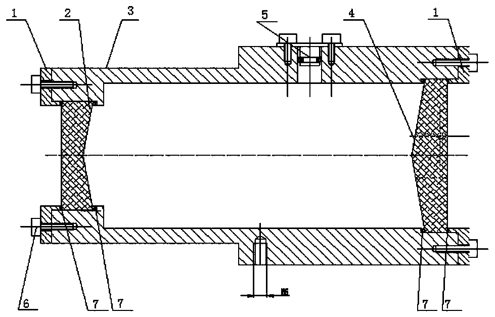
[0042] like figure 2 and Figure 4 As shown, the combined axicon device structure of the present embodiment includes a gland 1, a negative axicon 2, a positive axicon 4, between the negative axicon 2 and the positive axicon 4, and with the negative axicon 2 and the positive axicon The shape of 4 matches the optical medium, the lens barrel 3, the sealing plug 5, the nut 6 and the gasket 7;

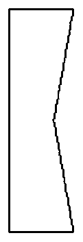
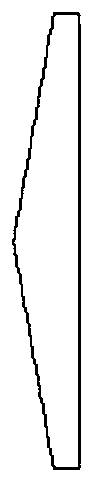
[0043] The concave cone surface of described negative axicon 2 is opposite to the convex cone surface of positive axicon 4; Wherein Fig. 1 (a) is negative axicon structure schematic diagram of the present invention; Fig. 1 (b) is positive axicon structure of the present invention schematic diagram;

[0044] The negative axicon 2 and the positive axicon 4 are respectively fixed at the two ends of the lens barrel 3, and the contact surfaces of the negative axicon 2, the positive axicon 4 and the lens barrel 3 are provided with gaskets 7;

[0045] The lens barrel 3, that is, the space betwe...

Embodiment 2

[0049] like image 3 and Figure 5As shown, the combined axicon device structure of the present embodiment is designed as a slidable structure, including a gland 1, a negative axicon 2, a positive axicon 4, between the negative axicon 2 and the positive axicon 4, and with the negative The optical medium whose shape matches the axicon 2 and the positive axicon 4, the lens barrel 3, the sealing plug 5, the nut 6, the gasket 7 and the sliding cylinder 8;

[0050] The concave cone surface of described negative axicon 2 is opposite to the convex cone surface of positive axicon 4; Wherein Fig. 1 (a) is negative axicon structure schematic diagram of the present invention; Fig. 1 (b) is positive axicon structure of the present invention schematic diagram;

[0051] The sliding tube 8 is matched and nested in the lens barrel 3;

[0052] The negative axicon 2 is fixed on the nesting end of the slide tube 8 and the lens barrel 3, and the positive axicon 4 is fixed on the other end of t...


PUM

PropertyMeasurementUnit
refractive indexaaaaaaaaaa

Abstract

The invention provides a combined axicon device, which uses a negative axicon and a positive axicon to form a combined axicon device, and through the replacement of the filling medium between the positive and negative axicons or the change of the distance between the positive and negative axicons, the traditional combined axicon The pyramid breaks through the limitation of the base angle of the uniaxial pyramid, and produces a high-quality, long-distance non-diffraction beam. Changing the refractive index of the optical medium between the positive and negative axicons can change the maximum non-diffraction distance of the combined axicon device. It is conducive to the tuning of parameters such as the non-diffraction distance; at the same time, the combined axicon device in the present invention is beneficial to reduce the processing difficulty of a single element, thereby reducing the processing cost and expanding the application of the non-diffraction beam.

Description

technical field [0001] The invention belongs to the field of laser technology, in particular to a combined axicon device. Background technique [0002] The axicon is an optical element proposed by McLeod in 1954. The so-called axicon is a refraction or diffraction imaging axisymmetric optical element that can generate a hollow laser beam. The light passing through the axicon will continue to expand along its central axis. Approximate non-diffraction beams can be produced within a certain range. It has extremely important applications in the field of optics. Now there are various kinds of axicons, which can be divided into positive axicons and negative axicons according to their different functions. When the light beam passes through the axicon, after reflection and transmission, the light beam converges or diverges, but the common point is that they are all a conical lens, which constitute a conical focusing system. [0003] Since Dumin proposed non-diffraction Bessel (Be...

Claims


Application Information

Patent Timeline
Patent Type & Authority Patents(China)
IPC IPC(8): G02B5/00G02B27/09G02B7/00
CPCG02B7/00G02B27/095G02B5/001
Inventor 黄秀军刘亮徐红艳宋镇江张翠翠王凯明石德乐
Owner SHANDONG INST OF AEROSPACE ELECTRONICS TECH
Learn More