Grain quality discrimination device
A technology for distinguishing devices and grains, applied in measuring devices, testing moving fluids/granular solids, applications, etc., can solve problems such as instability, inability to correct, and high cost, achieve stable grade discrimination accuracy, and improve discrimination accuracy , the effect of labor reduction
- Summary
- Abstract
- Description
- Claims
- Application Information
AI Technical Summary
Problems solved by technology
Method used
Image
Examples
Embodiment approach 1—1
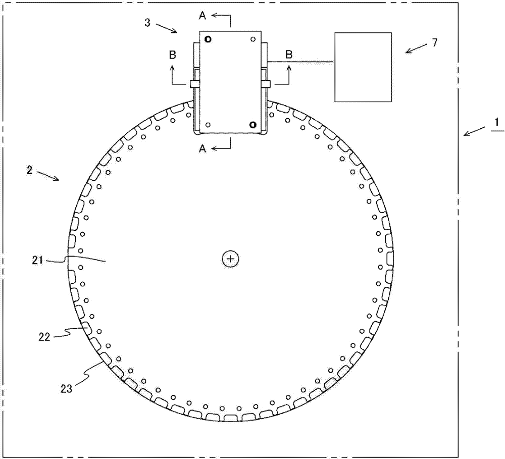
[0086] figure 1 It is a schematic explanatory drawing of the grain grade discrimination|determination apparatus of Embodiment 1-1 of this invention.
[0087] Grain grade discriminating device 1 is provided with: conveyance part 2, conveys grain G; Optical part 3, irradiates light to above-mentioned grain G, receives the reflected light and / or transmitted light from above-mentioned grain G; And grade discriminating part 7 , to judge the grade of the above-mentioned grain G.
[0088] The conveyance unit 2 has a disk 21 that is rotationally driven by a drive motor not shown. A plurality of recesses 22 are formed at peripheral positions of the disk 21 , and a transparent bottom plate 23 is disposed on the recesses 22 .
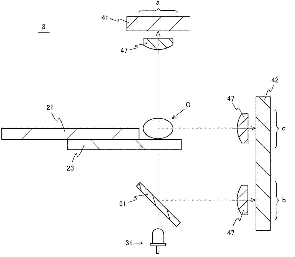
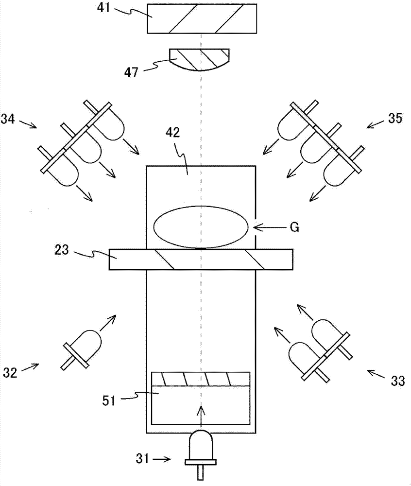
[0089] The said optical part 3 has the light source which irradiates the grain G with light, and the sensor which receives the reflected light and / or transmitted light from the said grain G of the light irradiated from the said light source. The optical unit 3 ...
Embodiment approach 1—2
[0120] Figure 4 It is an explanatory drawing showing the optical part of Embodiment 1-2 of the present invention.
[0121] In this embodiment, a dichroic filter is used that has the characteristics of reflecting blue light among the three primary colors of red (R), green (G), and blue (B) light, and transmitting green light and red light. The dichroic long-pass filter 52.
[0122] The above-mentioned dichroic long-pass filter 52 is arranged on the back side of the grain G with respect to the rotation surface of the above-mentioned disc 21 and the above-mentioned side light receiving sensor 42 with an inclination angle of forty-five degrees between the grain G and the blue. Between the color light source 31.
[0123] Moreover, the reflection material 61 is arrange|positioned parallel to the said dichroic long pass filter 52 between the said grain G and the said dichroic long pass filter 52.
[0124] Here, in the present invention, a mirror is used for the reflector 61 descr...
Embodiment approach 1—3
[0134] Figure 5 It is an explanatory diagram showing the optical part of Embodiment 1-3 of the present invention.
[0135] The difference between the optical unit 3 of Embodiments 1-3 of the present invention and the optical unit 3 of Embodiment 1 is that the light receiving sensor is arranged only on the side surface side of the grain G and is arranged so as to be able to point to the circle of the conveying unit 2 . The side surface side photosensor 42 that scans in a direction perpendicular to the rotation plane of the disk 21 is constituted.
[0136] The above-mentioned side light-receiving sensor 42 includes: a light-receiving area a for the surface, which receives reflected light and / or transmitted light from the front side of the above-mentioned grain G; light and / or transmitted light; and the light receiving area c for side surfaces which receives the reflected light and / or transmitted light from the side surface side of the said grain G.
[0137] In addition, in Em...
PUM
 Abstract
Description
Claims
Application Information
 - R&D
- Intellectual Property
- Life Sciences
- Materials
- Tech Scout
- Unparalleled Data Quality
- Higher Quality Content
- 60% Fewer Hallucinations
Browse by: Latest US Patents, China's latest patents, Technical Efficacy Thesaurus, Application Domain, Technology Topic, Popular Technical Reports.
© 2025 PatSnap. All rights reserved.Legal|Privacy policy|Modern Slavery Act Transparency Statement|Sitemap|About US| Contact US: help@patsnap.com


