

Optical lens polishing device and polishing technology
A technology of optical lens and polishing device, which is applied in the direction of grinding device, grinding/polishing equipment, abrasive surface adjustment device, etc. It can solve the problems of lens deformation, cumbersome operation, and low efficiency, so as to correct the surface error and improve the polishing effect , the effect of uniform force
- Summary
- Abstract
- Description
- Claims
- Application Information
AI Technical Summary
Problems solved by technology
Method used
Image

Examples
Embodiment approach
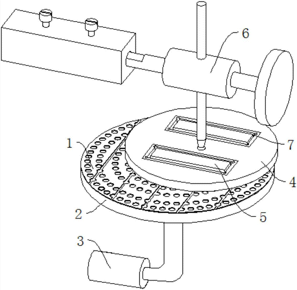
[0031] Referring to the accompanying drawings, in one embodiment of the present invention: an optical lens polishing device, comprising: a polishing pad 1, a polishing pad base 2, a driving device 3, a separator 4, a pressing block 5 and a polishing machine 6; a polishing pad 1 is a polyurethane material, which is bonded to the polishing pad base 2 through a thermosetting adhesive such as epoxy resin or silicone, and the polishing pad base 2 moves under the drive of the driving device 3; the separator 4 is placed on the polishing pad 1, and the separator 4 A plurality of load tanks 7 are arranged on the top, and the load tank 7 can be in any shape such as a square or a circle, and a protective cover is provided on the inner wall of the load tank 7; the pressing block 5 is movably placed in the load tank of the separator 4 ; There is a hole in the middle of the separator 4, and the thimble on the polishing machine 6 is inserted into the hole of the separator 4. The polishing pa...
PUM
| Property | Measurement | Unit |
|---|---|---|
| Granularity | aaaaa | aaaaa |
Abstract
Description
Claims
Application Information