Physical simulator of thick oil thermal extraction based on vacuum method and working method of physical simulator

A technology of thermal recovery and working method of heavy oil, which is applied in the direction of production fluid, earthwork drilling, wellbore/well components, etc., which can solve the problems of inability to truly reflect the thermal recovery effect, high steam heat loss, and unsatisfactory steam heat transfer and heat preservation treatment and other problems, to achieve the effect of authenticity and reliability of experimental results, reduction of errors, and excellent vacuum insulation performance

Inactive Publication Date: 2017-10-17
CHINA UNIV OF PETROLEUM (EAST CHINA)
View PDF8 Cites 2 Cited by
  • Summary
  • Abstract
  • Description
  • Claims
  • Application Information

AI Technical Summary

Problems solved by technology

Heavy oil thermal recovery technologies mainly include steam huff and puff, steam flooding, SAGD, hot water flooding, oil layer combustion, etc. Among them, steam huff and puff and steam flooding technologies are the most commonly used thermal recovery technologies at present. In order to develop heavy oil by steam injection, many indoor Experimental devices emerged as the times require, but at present, the thermal insulation treatment of steam heat transfer in these devices is not ideal during the experiment process. The heat loss of injected steam is large, and the oil layer cannot be fully added. The experimental results obtained cannot truly reflect the thermal recovery effect.

Method used


Image

  • Physical simulator of thick oil thermal extraction based on vacuum method and working method of physical simulator

Examples


Embodiment 1

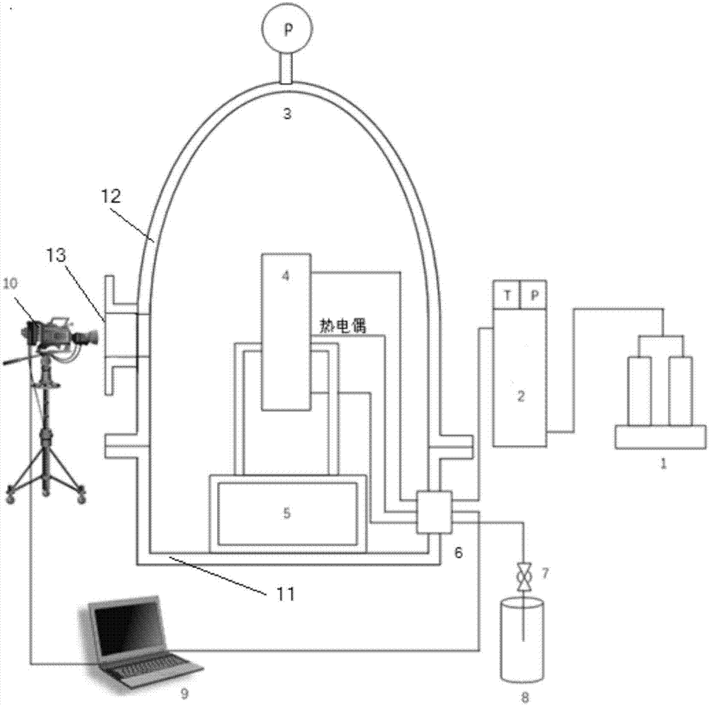
[0030] A physical simulation device for thermal recovery of heavy oil based on vacuum method and its working method, including:

[0031] Vacuum insulation cabin: vacuumize the insulation cabin;

[0032] Experimental model: set in the vacuum insulation cabin, used to inject steam to simulate the thermal recovery process of heavy oil; the experimental model includes: quartz sand, injection well and production well;

[0033] Steam generating part: arranged outside the vacuum insulation cabin, connected to the experimental model through pipelines;

[0034] Production fluid recovery pipeline: used to recover production fluid during heavy oil thermal recovery.

Embodiment 2

[0036] A physical simulation device for thermal recovery of heavy oil based on the vacuum method and its working method as described in Example 1, the difference is that the vacuum heat insulation cabin includes a bottom tank and a hatch cover that are connected to each other by buckling flanges.

Embodiment 3

[0038] A physical simulation device for thermal recovery of heavy oil based on vacuum method and its working method as described in Example 2, the difference is that the inner diameter of the vacuum insulation cabin is 1000-1500mm, and the height of the vacuum insulation cabin is 1200-2000mm.


PUM


Abstract

Provided are a physical simulator of thick oil thermal extraction based on a vacuum method and a working method of the physical simulator. The physical simulator comprises a vacuum thermal insulation cabin which can be vacuumized, an experimental model which is arranged in the vacuum thermal insulation cabin and used for injecting steam to simulate a process of the thick oil thermal extraction, a steam generating part and an output liquid recovery pipeline, wherein the experimental model comprises quartz sand, an injection well and a production well, the steam generating part is arranged outside the vacuum thermal insulation cabin and connected with the experimental model through a pipeline, and the output liquid recovery pipeline is used for recovering output liquid in the thick oil thermal extraction process. The physical simulator of thick oil thermal extraction based on a vacuum method and a working method of the physical simulator not only can achieve continuous collection of temperature data at different positions of the experimental model and continuous tracking of the location of a steam-crude oil interface, but also greatly reduce experimental error due to the excellent vacuum insulation performance of the physical simulator, and provide great convenience for direct observation and theoretical analysis of the formation and expansion of a steam chamber in the steam-injected thermal production process of oil; moreover, the obtained experimental results are real and reliable.

Description

technical field [0001] The invention relates to a physical simulation device for heavy oil thermal recovery based on a vacuum method and a working method thereof, and belongs to the technical field of crude oil measurement devices. Background technique [0002] Due to its high colloidal asphaltene content and high viscosity, heavy oil has difficulty in flowing and mining. As the main means of heavy oil recovery, thermal recovery technology has been widely used in various heavy oil reservoirs at home and abroad and has achieved significant production increase effects. Heavy oil thermal recovery technologies mainly include steam huff and puff, steam flooding, SAGD, hot water flooding, oil layer combustion, etc. Among them, steam huff and puff and steam flooding technologies are the most commonly used thermal recovery technologies at present. In order to develop heavy oil by steam injection, many indoor Experimental devices have emerged as the times require, but at present, th...

Claims


Application Information

Patent Timeline
Patent Type & Authority Applications(China)
IPC IPC(8): E21B43/24
CPCE21B43/24
Inventor 鹿腾李兆敏王宏远侯大炜杨建平王诗中
Owner CHINA UNIV OF PETROLEUM (EAST CHINA)
Why Eureka
Try Eureka