Hydraulic support manual electrohydraulic control system

An electro-hydraulic control system and hydraulic support technology, which is applied in mine roof support, mining equipment, earthwork drilling and mining, etc., can solve problems such as difficult operation, low reliability, and poor straightening function of the working face

Inactive Publication Date: 2017-10-17
丰隆高科液压股份有限公司
View PDF4 Cites 4 Cited by
  • Summary
  • Abstract
  • Description
  • Claims
  • Application Information

AI Technical Summary

Problems solved by technology

[0002] With the improvement of comprehensive mechanized coal mining technology, a large number of hydraulic supports in the world's major coal mining countries are equipped with electro-hydraulic control valves; among them, automation has become an important symbol to measure the level of coal mining technology, and its development will save miners from monotonous and repetitive It can be liberated from the highly flexible working environment and engage in more creative work; however, most of the supports used for mechanical coal mining adopt fully automatic electro-hydraulic control systems, and the operation of fully automatic electro-hydraulic control systems requires writing complex programs and requiring a large number of various There are several types of sensor support; then configuring a large number of sensors requires a large amount of wiring. In this case, in the harsh environment of the working surface, it will be difficult to operate, and the maintenance workload is huge, the reliability is not high, and it is impossible to realize a single There are many problems such as positioning between shearers, poor straightening function of the working face, and difficult coal discharge control; in addition, the automatic control system cannot effectively control a large number of fully automatic control hydraulic supports, and still needs to rely on artificial intervention and control

Method used


Image

  • Hydraulic support manual electrohydraulic control system
  • Hydraulic support manual electrohydraulic control system
  • Hydraulic support manual electrohydraulic control system

Examples


Embodiment Construction

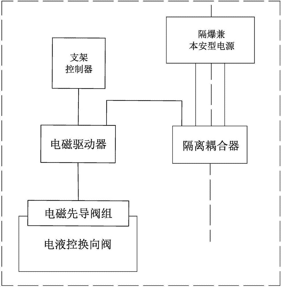
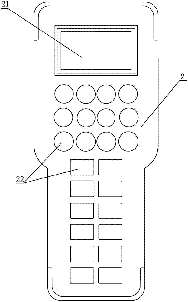
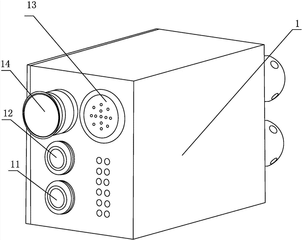
[0023] Such as figure 1 As described in -3, the specific embodiment of the present invention adopts a manual electro-hydraulic control system of a hydraulic support, which is controlled by a flameproof and intrinsically safe power supply, an electromagnetic driver 1, an electro-hydraulic control reversing valve, an isolation coupler and a hand-held support The electro-hydraulic control reversing valve is composed of an electromagnetic pilot valve and a main control valve. The explosion-proof and intrinsically safe power supply, the electromagnetic driver 1, the electro-hydraulic control reversing valve and the isolation coupler are all set on the hydraulic support body. And the explosion-proof and intrinsically safe power supply, the isolation coupler, the electromagnetic driver 1 and the electro-hydraulic control reversing valve are sequentially connected through cables. The manual electro-hydraulic control system of the hydraulic support is also provided with a communication ...


PUM


Abstract

The invention discloses a hydraulic support manual electrohydraulic control system which comprises an electrohydraulic control commutating valve, an actuator, a power supply and an isolated coupling machine. The hydraulic support manual electrohydraulic control system also comprises a handheld stent controller connected with the actuator. According to the system, a plurality of sensors in a full-automatic control hydraulic support can be omitted, so that a plurality of lines needed in a working surface because of assignment of the sensors are omitted, and a lot of maintenance charges are omitted; through the handheld stent controller, the position of a coalcutter is determined, the working face is helped to be aligned, and coal caving position is accurately controlled; the hydraulic support manual electrohydraulic control system has the advantages of a traditional hydraulic support electrohydraulic control system that operation is simple, labor intensity is low, and remote safe control is practicable, and accordingly application space of electrohydraulic control system is largely expanded; the hydraulic support manual electrohydraulic control system adapts to actual production of a coal mining working face, so that automation level and security and reliability of a first production line are improved.

Description

technical field [0001] The invention relates to an electro-hydraulic control system, in particular to a manual electro-hydraulic control system of a hydraulic support. Background technique [0002] With the improvement of comprehensive mechanized coal mining technology, a large number of hydraulic supports in the world's major coal mining countries are equipped with electro-hydraulic control valves; among them, automation has become an important symbol to measure the level of coal mining technology, and its development will save miners from monotonous and repetitive It can be liberated from the highly flexible working environment and engage in more creative work; however, most of the supports used for mechanical coal mining adopt fully automatic electro-hydraulic control systems, and the operation of fully automatic electro-hydraulic control systems requires writing complex programs and requiring a large number of various There are several types of sensor support; then confi...

Claims


Application Information

Patent Timeline
Patent Type & Authority Applications(China)
IPC IPC(8): E21D23/16
CPCE21D23/16
Inventor 洪凌海李竹洋王琛朱小平张冰珏
Owner 丰隆高科液压股份有限公司
Why Eureka
Try Eureka