LED lamp

A technology of LED lamps and lamp holders, which is applied in the direction of lampshades, lighting devices, light sources, etc., can solve problems such as glare, unsatisfactory heat dissipation, and impact on product life, so as to reduce equipment investment and energy consumption, reduce fixed asset investment, and easily The effect of automated production

Inactive Publication Date: 2017-10-17
丁大为
View PDF8 Cites 1 Cited by
  • Summary
  • Abstract
  • Description
  • Claims
  • Application Information

AI Technical Summary

Problems solved by technology

[0003] First of all, the entire production process of the LED filament lamp includes assembling the light bar and the glass stem, vacuuming, filling helium, etc. The production process is complicated and it is difficult to realize automatic production
At the same time, in the production process, high temperature, vacuum, helium and large-scale production equipment are required, and a large number of production preparations are required before production. Some processes are as complicated as traditional incandescent lamps, and the process is difficult and the production capacity is limited.
Secondly, the LED filament lamp needs to convect the helium inside the bulb to the bulb for heat dissipation. The heat dissipation is not ideal, and the product life is affected. In addition, the production process consumes a lot of natural gas and consumes a lot of energy.
Thirdly, the light bar of the LED filament lamp needs to be fixed on the stem and there needs to be a space between the two, and the uneven light mixing will easily form a dark area
Fourth, the LED light strip is oriented directly to the transparent glass bulb, and the light is dazzling

Method used


Image

  • LED lamp
  • LED lamp
  • LED lamp

Examples


Embodiment Construction

[0041] In order to make the technical problems, technical solutions and advantages to be solved by the present invention clearer, the following will describe in detail with reference to the drawings and specific embodiments.

[0042]It should be noted that the terms "first" and "second" in the description and claims of the present invention are used to distinguish similar objects, but not necessarily used to describe a specific order or sequence. It is to be understood that the data so used are interchangeable under appropriate circumstances such that the embodiments of the invention described herein are, for example, capable of practice in sequences other than those illustrated or described herein.

[0043] An embodiment of the present invention provides an LED lamp, which may be an indoor or outdoor light source such as a ceiling lamp, a wall lamp, a desk lamp, a pendant lamp, a panel lamp, or a floor lamp. It should be noted that, in this embodiment, the type of the LED lam...


PUM


Abstract

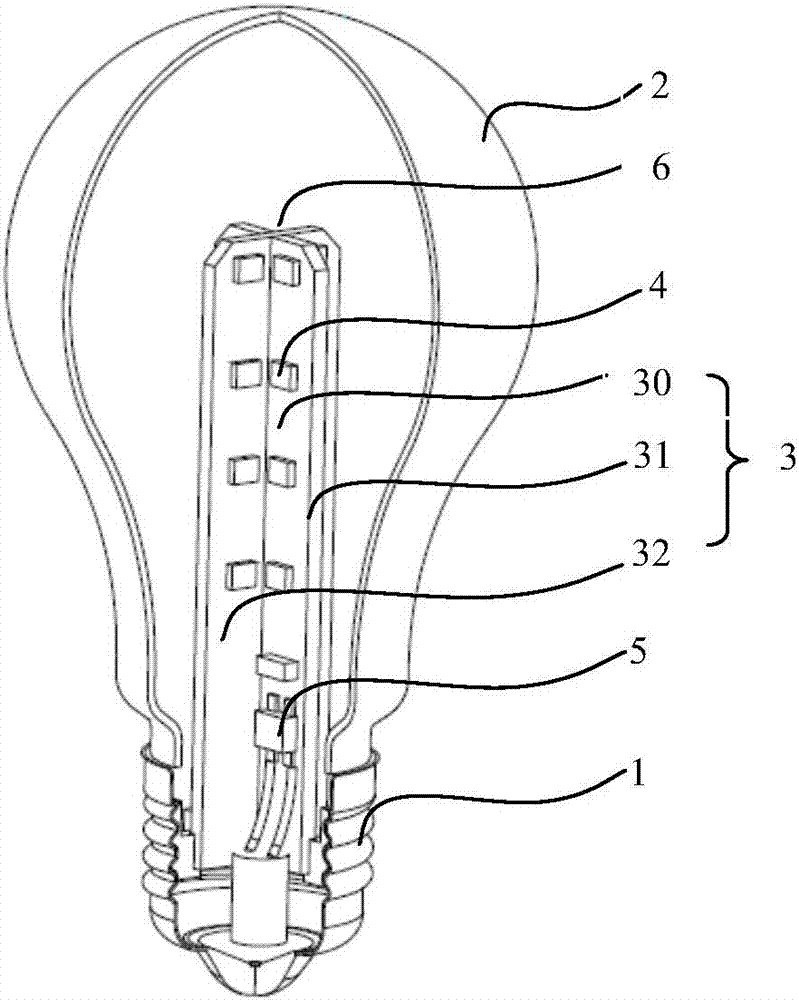
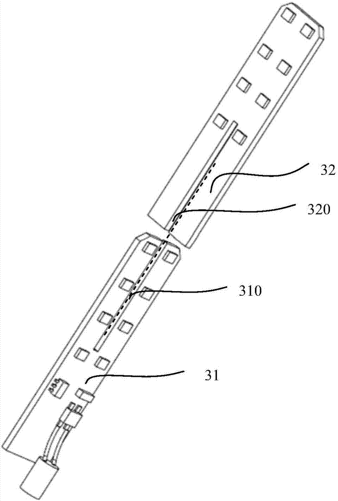
The embodiment of the invention provides an LED lamp. The LED lamp comprises a metal base plate structure, multiple LED units and a drive power circuit. The metal base plate structure comprises multiple structure surfaces, and the multiple LED units are fixed to the multiple structure surfaces of the metal base plate structure correspondingly, wherein the LED units on the structure surfaces are arranged in the long-axis direction of the LED lamp. Multiple light mixing areas are formed through reflection of at least part of light emitted by the multiple LED units through the multiple structure surfaces. The drive power circuit is fixed to the metal base plate structure, the power input end of the drive power circuit is used for being connected with a power supply, and the power output end of the drive power circuit is electrically connected with each LED unit. By means of the LED lamp in the embodiment, printed circuit boards are adopted, modularization can be achieved, and the assembling process of the LED lamp can be simplified. In addition, the LED lamp is good in heat dissipation, and inert gases such as helium do not need to be used for isolation.

Description

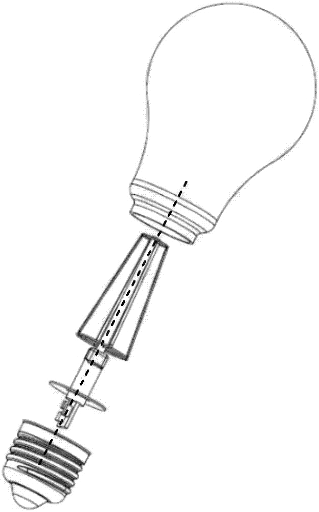
technical field [0001] The invention relates to the field of lighting lamps, in particular to an LED (Light Emitting Diode, light emitting diode) lamp. Background technique [0002] like figure 1 As shown in the figure, an existing LED filament lamp is shown in the figure. The light-emitting component of the LED filament lamp shown in the figure is a light bar (filament) type LED. The LED filament lamp has limitations in terms of production process and service life. In the production process of the LED filament lamp, it is necessary to first fix the light bar on the glass core column to form a lamp column, and then fix the entire lamp column inside the glass bulb, and fuse the glass bulb and glass core column into one body through high temperature. The seal becomes a hair bubble. At the same time, the inside of the bulb needs to be evacuated and then filled with helium to play the role of heat conduction and isolation protection. [0003] First of all, the entire producti...

Claims


Application Information

Patent Timeline
Patent Type & Authority Applications(China)
IPC IPC(8): F21K9/232F21V19/00F21K9/238F21K9/275F21K9/66F21V3/04F21Y115/10
CPCF21K9/232F21K9/238F21K9/275F21K9/66F21V3/04F21V19/003F21Y2115/10
Inventor 丁大为
Owner 丁大为
Why Eureka
Try Eureka