Angle compensation type laser heterodyne interference displacement measuring device and angle compensation type laser heterodyne interference displacement measuring method

A technology of laser heterodyne interference and displacement measurement, which is applied in the direction of measuring devices, optical devices, instruments, etc., can solve the problems of rotation angle error affecting the accuracy of displacement measurement, and achieve the effect of rotation angle detection and high-precision displacement measurement

Pending Publication Date: 2017-10-17
ZHEJIANG SCI-TECH UNIV
View PDF6 Cites 17 Cited by
  • Summary
  • Abstract
  • Description
  • Claims
  • Application Information

AI Technical Summary

Problems solved by technology

[0003] In order to solve the technical problem in the traditional laser interferometric displacement measurement technology that the corner angle error of the corner cube affects the displacement m

Method used


Image

  • Angle compensation type laser heterodyne interference displacement measuring device and angle compensation type laser heterodyne interference displacement measuring method
  • Angle compensation type laser heterodyne interference displacement measuring device and angle compensation type laser heterodyne interference displacement measuring method
  • Angle compensation type laser heterodyne interference displacement measuring device and angle compensation type laser heterodyne interference displacement measuring method

Examples


Embodiment Construction

[0049] The present invention will be further described below in conjunction with drawings and embodiments.

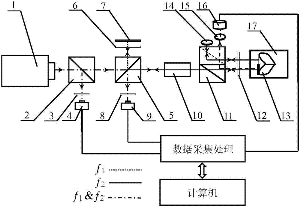
[0050] Optical path structure of the present invention such as figure 1 As shown, it includes the laser heterodyne interference displacement measurement part and the laser spot detection rotation angle measurement part. The specific implementation process is as follows:

[0051] A) Laser heterodyne interference displacement measurement part

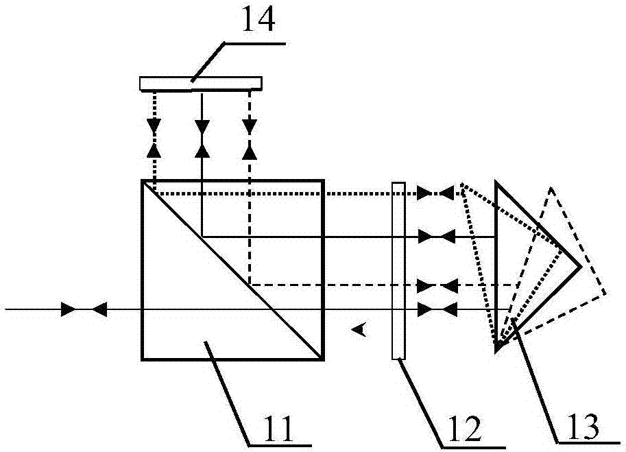
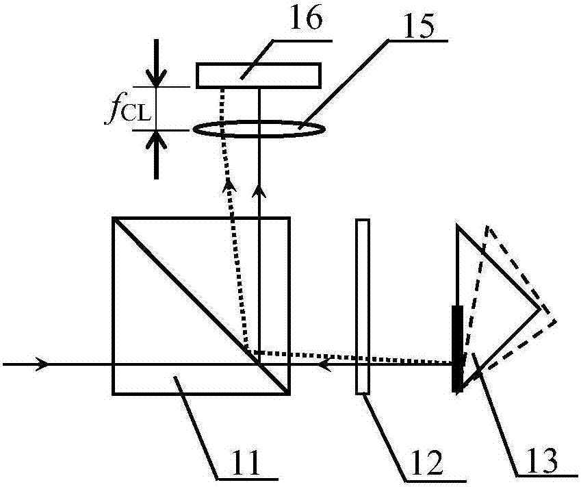
[0052] It includes a laser heterodyne interference displacement measurement optical path part and a corner cube prism 13. The laser heterodyne interference displacement measurement optical path part includes a dual-frequency laser 1 capable of outputting orthogonal linearly polarized light, a first beam splitter 2, a first polarizer 3, a second A photodetector 4, a first polarization beam splitter 5, a first quarter-wave plate 6, a first plane mirror 7, a second polarizer 8, a second photodetector 9, a Faraday rotator 10, and a se...


PUM


Abstract

The invention discloses an angle compensation type laser heterodyne interference displacement measuring device and an angle compensation type laser heterodyne interference displacement measuring method. A cube-corner prism provided with a semi-transparent semi-reflecting film in a coated manner is used as a measuring mirror used for measuring displacement and a corner, and an interference signal generated by a laser heterodyne interference optical path is detected by a photoelectric detector, and after data acquisition processing, a displacement measuring initial value is acquired. After data acquisition processing of a laser spot position signal generated by a laser spot detection corner measuring optical path, a pitch angle error value and a deflection angle error value of a measured object are acquired, and then a corner value required by displacement compensation is acquired. The initial value is compensated by using the corner value, and a final displacement measuring value is acquired. A technical problem of a conventional laser heterodyne displacement measuring technology of influences of corner errors of cube-corner prisms on displacement measuring precision is solved, and therefore high-precision displacement measurement is realized, and the three freedom degrees of the measured object such as the deflection angle, the pitch angle, and the linear displacement are detected at the same time.

Description

technical field [0001] The invention relates to a laser heterodyne interference displacement measurement method, in particular to an angle compensation type laser heterodyne interference displacement measurement device and method. Background technique [0002] Due to the characteristics of large measurement range, high measurement accuracy and direct traceability of length reference, laser interferometry technology is widely used in precision machining and manufacturing, measurement and calibration of precision instruments and other fields to achieve displacement measurement. Traditional laser interferometric displacement measurement technology can be roughly divided into single-frequency laser interferometric displacement measurement system and laser heterodyne interferometric displacement measurement system according to the type of light source used in the interference system. The displacement measurement optical path structure in these two interferometric systems is basica...

Claims


Application Information

Patent Timeline
IPC IPC(8): G01B11/02G01B11/26G01B9/02
CPCG01B9/02058G01B9/02061G01B11/02G01B11/26Y02A90/10
Inventor 张恩政陈本永
Owner ZHEJIANG SCI-TECH UNIV
Why Eureka
Try Eureka