Laser device with a beam carrying controlled orbital angular momentum

A laser device and light wave technology, applied in the direction of lasers, laser components, semiconductor lasers, etc., can solve problems such as incomprehension, complicated alignment process, unclear selection, etc., and achieve good coherence, good stability, and simplified The effect of the design

Inactive Publication Date: 2017-10-17
UNIVERSITY OF MONTPELLIER +1
View PDF1 Cites 9 Cited by
  • Summary
  • Abstract
  • Description
  • Claims
  • Application Information

AI Technical Summary

Problems solved by technology

However, it is inconvenient that both methods require intracavity components (absorbers, apertures, Brewster windows, collimators, etc.), which lead to complex alignment procedures and affect the spatial coherence of the beam
Also, the choice of direction of wavefront rotation is unclear or not understood

Method used


Image

  • Laser device with a beam carrying controlled orbital angular momentum
  • Laser device with a beam carrying controlled orbital angular momentum
  • Laser device with a beam carrying controlled orbital angular momentum

Examples


Embodiment Construction

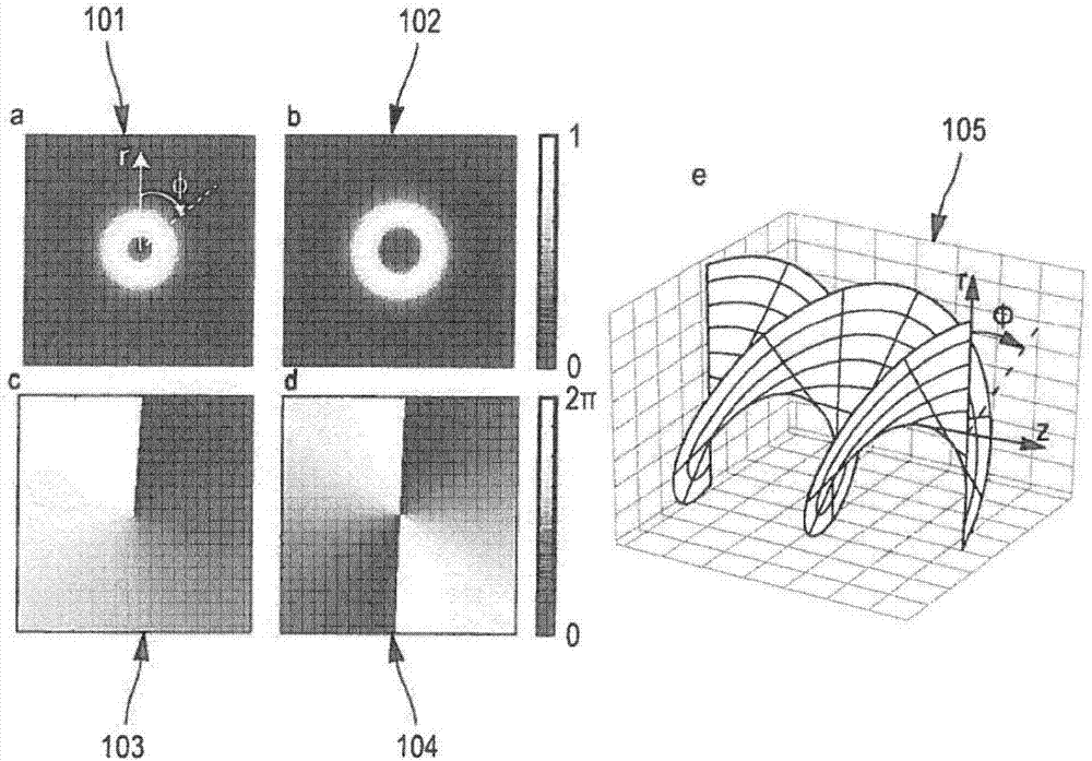
[0084] Hereinafter, the adjectives "longitudinal" and "azimuthal" refer to directions corresponding to one of the light wave propagation or the cavity axis, while the adjectives "transverse" and "radial" refer to directions orthogonal to the longitudinal direction. direction.

[0085] The adjective "azimuthal" refers to an angle measured in the transverse plane and obtained by a given rotation along the longitudinal axis.

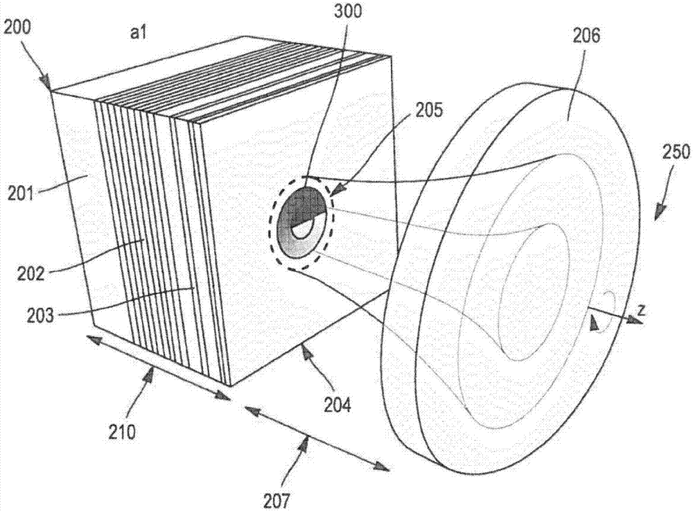
[0086] In the ensuing description, without limiting the present invention, the first element 200 is considered to be a semiconductor element.

[0087] As mentioned above, the present invention aims at selecting the rotationally symmetric transverse modes of the light waves oscillating in the optical cavity. One of these modes is Laguerre-Gauss with a radial index equal to 0 and an azimuthal index that is a non-zero integer. It can be positive or negative. In another embodiment, it may also be a non-integer value corresponding to an imperfect choice of ei...


PUM


Abstract

A laser device (250) for generating a helical-shaped optical wave and comprising: (i) a gain region (203) located between one first end defined by a first mirror (202) and a second end defined by an exit region, (ii) a second mirror (206) arranged so as to form with the first mirror (202) an optical cavity including the gain region (203) and a gap (207) between the exit region and the second mirror (206), (iii) means for pumping the gain region (203) so as to generate the optical wave, wherein the laser device (250) further comprises at least one means for shaping the light intensity and / or phase profiles of the optical wave and arranged for selecting at least one rotary-symmetrical transverse mode of the optical wave, said rotary-symmetrical transverse mode being chosen between those with a radial index equal to zero and with an azimuthal index being an integer with a module higher or equal to 1.

Description

technical field [0001] The present invention relates to vertical external-cavity surface-emitting laser devices (VeCSELs), and more particularly to the use of such devices to generate coherent single-frequency vortex modes or dual-frequency vortex modes. [0002] The technical field of the invention is, but not limited to, photonic applications, more precisely optical manipulation of microscopic particles, atomic manipulation, sub-diffraction microscopy, and quantum information processing and communication. Background technique [0003] A beam of helical phase, also called a vortex beam, exhibits a helical wavefront that varies in a helical-like fashion along the beam propagation direction, with a Poynting vector following a helical trajectory around the beam axis. Through the azimuthal phase term e in the field expression iMθ to describe this behavior, where the factor M is called the topological charge, which can be both positive and negative integer values ​​depending on...

Claims


Application Information

Patent Timeline
Patent Type & Authority Applications(China)
IPC IPC(8): H01S5/14H01S5/183H01S5/10
CPCH01S5/14H01S5/18319H01S2301/20H01S2301/203H01S5/11
Inventor 阿诺德·加尔纳什-克勒约米哈埃·穆亚拉伊莎贝尔·萨涅斯卢卡·勒格拉蒂耶穆罕默德·泽尔拉稀穆罕默德·赛格伊拉尼菲利浦·拉兰纳
Owner UNIVERSITY OF MONTPELLIER
Why Eureka
Try Eureka