Industrial waste gas treatment system

A technology of industrial waste gas and treatment system, which is applied in the fields of combination device, dispersed particle separation, chemical instrument and method, etc., can solve the problems of poor treatment effect, affecting the service life and treatment effect of high-voltage static electricity, and unable to meet the requirements of industrial waste gas treatment, etc. Achieve the effect of reducing the adhesion of oil droplets and ensuring the effect of oil fume separation

Pending Publication Date: 2017-10-20
佛山市科思博科技有限公司
View PDF7 Cites 5 Cited by
  • Summary
  • Abstract
  • Description
  • Claims
  • Application Information

AI Technical Summary

Problems solved by technology

[0004] The embodiment of the present invention discloses an industrial waste gas treatment system to solve the problem that the existing industrial waste gas treatment system has poor treatment effect, cannot meet the requ

Method used


Image

  • Industrial waste gas treatment system
  • Industrial waste gas treatment system
  • Industrial waste gas treatment system

Examples


Embodiment 1

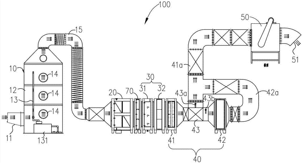
[0070] See figure 1, the first embodiment provides an industrial waste gas treatment system 100, including a spray device 10, an oil fume separation device 20, a smoke removal device 30, an odor removal device 40 and a fan 50, and the spray device 10 is provided with a waste gas inlet 11 and a liquid injection Assemblies (not shown), the exhaust gas inlet 11 communicates with the inside of the spraying device 10 , and the liquid injection assembly is arranged in the spraying device 10 . The smoke removal device 30, the deodorization device 40 and the fan 50 are sequentially connected and arranged outside the spray device 10. The fan 50 is provided with an air outlet 51. Industrial waste gas enters the spray device 10 from the waste gas inlet 11 and is sprayed by a liquid injection assembly to remove dust. After that, it is transported to the oil fume separation device 20 for oil fume separation, and then sequentially transported to the smoke removal device 30 and the deodoriza...

Embodiment 2

[0106] Please also refer to Figure 6 to Figure 7 , is a structural diagram of an industrial waste gas treatment system 200 provided in Embodiment 2 of the present invention. The difference between the industrial waste gas treatment system 200 of the second embodiment of the present invention and the industrial waste gas treatment system 100 of the first embodiment of the present invention is that:

[0107] A baffle plate 17 is arranged in the shower device 10, and the baffle board 17 divides the shower device 10 into a first part 10a and a second part 10b. The first part 10a is provided with a gas passage 101 leading to the second part 10b. The liquid The injection assembly is arranged in the first part 10a, and the oil fume separation device 20 is arranged in the second part 10b. That is to say, in this embodiment, the oil fume separation device 20 is disposed inside the spray device 10 . With this arrangement, the overall volume of the industrial waste gas treatment syste...


PUM


Abstract

The invention discloses an industrial waste gas treatment system, which consists of a spraying device, an oil fume separation device, a fume removal device, a smell removal device and a fan. The spraying device is equipped with a waste gas inlet and a liquid jet component, the waste gas inlet is communicated with the inside of the spraying device, the liquid jet component is disposed in the spraying device, the fume removal device, the smell removal device and the fan are connected in order and are disposed outside the spraying device, the fan is equipped with an air outlet, industrial waste gas enters the spraying device through the waste gas inlet and undergoes jetting dedusting by the liquid jet component, then the industrial waste gas is conveyed to the oil fume separation device for oil fume separation, then the treated industrial waste gas is sent to the fume removal device and smell removal device in order for fume removal and smell removal, and then the treated industrial waste gas is discharged through the air outlet of the fan. According to the invention, the oil fume separation device and the fume removal device are separated, the oil fume separation device is utilized to remove oil drops from oil fume, adsorption of a lot of oil drops on the fume removal device can be avoided, frequent cleaning or replacement of the fume removal device is unnecessary, and the cleaning workload and fume removal device maintenance workload of a user can be reduced.

Description

technical field [0001] The invention relates to the technical field of oil fume purification, in particular to an industrial waste gas treatment system. Background technique [0002] At present, whether it is household appliances and furniture in people's daily life, or large-scale equipment such as production equipment in factories, railway road bridges, ships, and aircraft, industrial coatings (such as paints) are required. However, whether industrial coatings are in the production process or in the process of spraying and brushing, industrial waste gas (mainly including paint mist, harmful gases, etc.) is likely to be generated. , Threat to the health of workers. In addition, if the industrial waste gas is directly discharged into the atmosphere, it will also cause serious environmental pollution to the atmosphere. Therefore, it is necessary to treat this part of the industrial waste gas. [0003] At present, the existing treatment method for industrial waste gas of ind...

Claims


Application Information

Patent Timeline
IPC IPC(8): B01D50/00B01D53/00B01D53/02
CPCB01D50/00B01D53/007B01D53/02
Inventor 谢柳扬
Owner 佛山市科思博科技有限公司
Why Eureka
Try Eureka