
A mixer device for homogenization and clarification

A stirrer and stirring shaft technology, which is applied in the direction of manufacturing tools, glass furnace equipment, glass manufacturing equipment, etc., can solve the problems of crucible wall adhesion, increased loss, and large platinum consumption, so as to reduce clarification time and improve homogenization efficiency , Platinum low cost effect

Active Publication Date: 2020-08-04
HUBEI NEW HUAGUANG NEW INFORMATION MATERIALS CO LTD
View PDF5 Cites 0 Cited by
  • Summary
  • Abstract
  • Description
  • Claims
  • Application Information

AI Technical Summary

Problems solved by technology

In the patent CN 202046986 U, the method of bubbling and stirring is proposed to accelerate the homogenization of glass. The advantage of this method is that it can mix the upper and lower glass liquids and increase the homogenization speed. The disadvantage is that it is inconvenient to use and requires two or more One person looks at the position of the vent tube when it is lowered into the crucible, and one person puts and fixes the vent tube from the furnace top. At the same time, because the platinum vent tube is prone to deformation and bending at high temperature, it is easy to cause adhesion to the crucible wall. In severe cases, it may cause shutdown of the furnace
Patent CN 105174692 A proposes to add a stirrer above the general stirrer to speed up the homogenization. This method can improve the effect in theory, but it is rarely used in actual production. The platinum consumption is large and the loss is increased. , which is not conducive to cost saving, and cannot achieve the purpose of quickly mixing the upper and lower layers of glass liquid

Method used


Image

  • A mixer device for homogenization and clarification
  • A mixer device for homogenization and clarification
  • A mixer device for homogenization and clarification

Examples


Embodiment Construction

[0020] Various exemplary embodiments, features, and aspects of the invention will be described in detail below with reference to the accompanying drawings. The same reference numbers in the figures indicate functionally identical or similar elements. While various aspects of the embodiments are shown in drawings, the drawings are not necessarily drawn to scale unless specifically indicated.

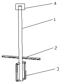
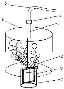
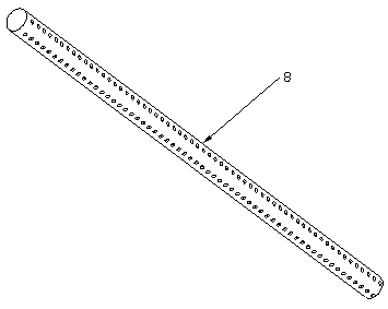
[0021] Embodiment 1 of a kind of high-efficiency homogenization and clarification agitator device provided by the present invention and its use status are as follows: Figure 1 to Figure 3 shown. Embodiment 1 includes a stirring shaft 1 , an air hole array tube 2 , a stirring frame 3 , a rotary ventilation joint 4 and an air pipe 5 . The stirring frame 3 is installed on the bottom of the stirring shaft 1, the stirring frame 3 is a rectangular outer frame, and the stirring frame 3 can also be a rectangular outer frame plus a cross-section in the rectangular outer frame, and the cross-sec...


PUM

PropertyMeasurementUnit
diameteraaaaaaaaaa

Abstract

The title of the invention is a homogenizing and clarifying agitator device. The invention belongs to the technical field of glass smelting. It mainly achieves the purpose of increasing the glass transmittance by improving the homogenization and clarification efficiency and shortening the melting time. Its main features are: including the stirring shaft, the air hole array tube or the air hole array tube and the stirring frame, and the rotating ventilation joint; among them, the air hole array tube is installed at the bottom of the stirring shaft, and the stirring frame or air hole array tube is installed at the bottom of the stirring shaft; the air hole Air holes are provided on the entire tube wall of the array tube; the stirring shaft is provided with an inner cavity with an open upper end, and the inner cavity communicates with the inner cavity of the air hole array tube; the upper end of the stirring shaft is provided with a rotary ventilation joint. The invention has the characteristics of simultaneously homogenizing the large-area upper and lower parts of the glass liquid in the crucible, gathering and floating the bubbles in the glass liquid, shortening the time of homogenization and clarification, and is mainly used for small batches or intermittent crucible clinker for experiments Preparation and production.

Description

technical field [0001] The invention belongs to the technical field of glass smelting, in particular to a stirring and homogenizing device for an intermittent crucible glass furnace. Background technique [0002] The optical glass used in small batches or experiments is generally produced in batch crucibles. This production method mainly uses agitator for homogenization or stirring and bubbling for homogenization. With the improvement of imaging quality requirements, the requirements for optical glass transmittance also increase. Therefore, major optical glass manufacturers have researched ways to increase transmittance. Shortening the homogenization or clarification time is the method to increase transmittance. one. In the patent CN 202046986 U, the method of bubbling and stirring is proposed to accelerate the homogenization of the glass. The advantage of this method is that it can mix the upper and lower glass liquids and increase the homogenization speed. The disadvantag...

Claims


Application Information

Patent Timeline
Patent Type & Authority Patents(China)
IPC IPC(8): C03B5/193
CPCC03B5/193
Inventor 陈超李建新周希光寇小勇王拓
Owner HUBEI NEW HUAGUANG NEW INFORMATION MATERIALS CO LTD
Learn More