Construction method for strengthening and water-retaining for I-shaped steel joint of underground diaphragm wall

An underground diaphragm wall and construction method technology, applied in artificial islands, sheet pile walls, water conservancy projects, etc., can solve problems such as complex operation, high site requirements, and inability to perform normal construction.

Active Publication Date: 2017-10-20
CHINA RAILWAY TUNNEL GROUP CO LTD
View PDF5 Cites 2 Cited by
  • Summary
  • Abstract
  • Description
  • Claims
  • Application Information

AI Technical Summary

Problems solved by technology

[0004] At present, for the water leakage at the I-steel joints of the diaphragm wall, stirring piles and rotary grouting piles are usually used to block the water to strengthen the soil, and there are also grouting reinforcements to stop the water, so as to control the leakage of the I-steel joints. Although the stirri

Method used


Image

  • Construction method for strengthening and water-retaining for I-shaped steel joint of underground diaphragm wall
  • Construction method for strengthening and water-retaining for I-shaped steel joint of underground diaphragm wall
  • Construction method for strengthening and water-retaining for I-shaped steel joint of underground diaphragm wall

Examples


Embodiment Construction

[0021] The technical solution of the present invention will be described in further detail below in conjunction with the accompanying drawings and embodiments.

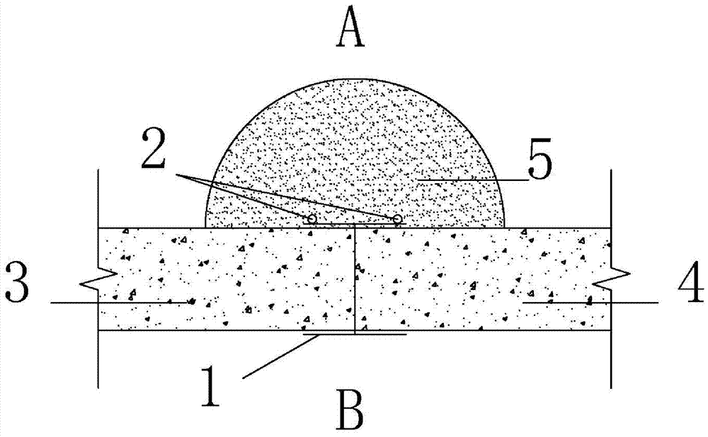
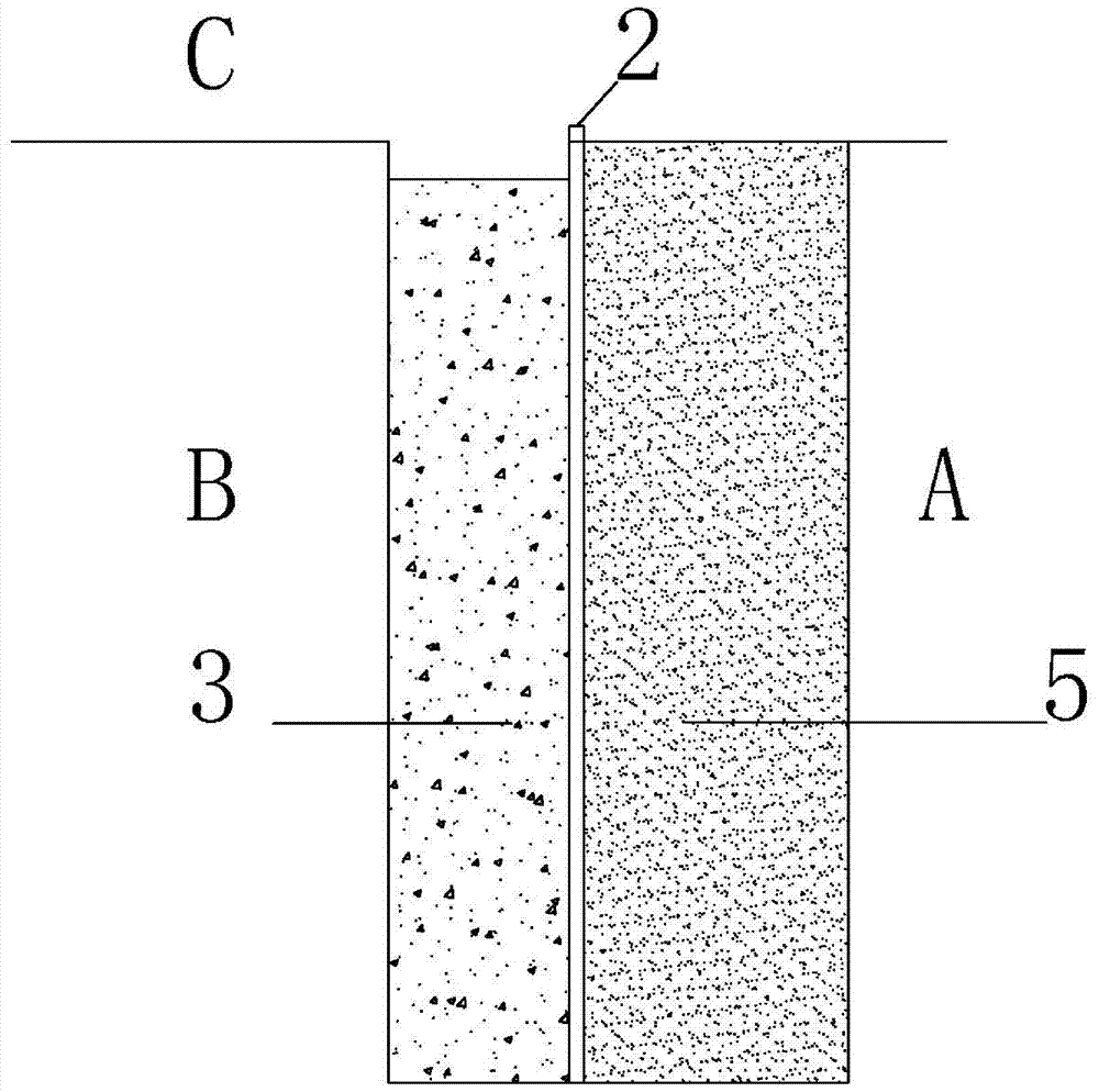
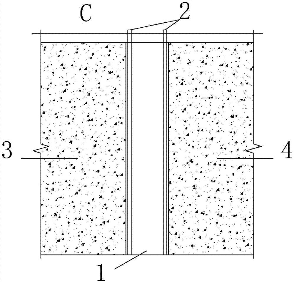
[0022] exist figure 1 , 2 , 3, A represents the facing soil side of the underground diaphragm wall, B represents the back soil side of the underground diaphragm wall, and C represents the ground.

[0023] The construction method for strengthening and sealing the I-shaped steel joints of the underground diaphragm wall includes the following specific steps:

[0024] Step 1. Weld the reinforcement cage in the first-phase construction groove section 3 of the underground diaphragm wall with the I-steel joint 1, and pre-embed two grouting grouts with a diameter of 25 to 30 mm on the side A of the flange plate facing the soil of the I-steel joint. Steel pipe 2; the top of grouting steel pipe 2 is 20-30cm higher than the ground C. The two grouting steel pipes are respectively located at both ends of the flange plate of the ...


PUM


Abstract

The invention discloses a construction method for strengthening and water-retaining for an I-shaped steel joint of an underground diaphragm wall. The construction method comprises the following steps: firstly, welding a steel reinforcement cage in a first-stage construction groove section of the underground diaphragm wall with the I-shaped steel joint, pre-embedding two grouting steel pipes in a near-soil side of a flange plate of the I-shaped steel joint, and locating the two grouting steel pipes at the two ends of the flange plate of the I-shaped steel joint separately; secondly, arranging the first-stage steel reinforcement cage in the first-stage construction groove section, and carrying out pouring working in the first-stage construction groove section; thirdly, arranging a second-stage steel reinforcement cage in a second-stage construction groove section, and carrying out pouring working in the second-stage construction groove section; and finally, after pouring working in the first-stage construction groove section and pouring working in the second-stage construction groove section are completed, connecting the grouting steel pipes with a grouting machine and carrying out grouting, and after the grouting working is completed, forming a semicircular strengthening area taking the I-shaped steel joint as the circle center and having a radius of 1.0-1.8m on the near-soil side of the I-shaped steel joint. The construction method disclosed by the invention is capable of improving the waterproofness of the I-shaped steel joint during construction for the underground diaphragm wall, so as to achieve a purpose of effectively controlling water leakage at the I-shaped steel joint.

Description

technical field [0001] The invention belongs to the technical field of underground diaphragm wall construction, and in particular relates to a construction method for reinforcing and sealing water at I-shaped steel joints of an underground diaphragm wall. Background technique [0002] With the continuous expansion of the scale of underground engineering construction in my country, especially the foundation pit enclosure project has reached an unprecedented scale. In the field of foundation pit enclosure structure construction, the underground diaphragm wall has the characteristics of small vibration, low It has the characteristics of high body rigidity, large construction depth, load bearing, good anti-seepage performance, and no disturbance to the surrounding foundation. It can be close to the original building and adapt to the construction of various complex strata. Therefore, it is designed and constructed in my country's underground projects. used widely. The underground ...

Claims


Application Information

Patent Timeline
IPC IPC(8): E02D29/16E02D5/18E02D5/20
CPCE02D5/187E02D5/20E02D29/16E02D2250/0023
Inventor 刘垚管泽英刘国良张泽卫许俊伟逄锦伟卢金栋代昱昊
Owner CHINA RAILWAY TUNNEL GROUP CO LTD
Why Eureka
Try Eureka