
Rigid roof cable-dome structure with circumferential-direction support

A cable dome and rigid technology, applied in the field of rigid roof cable dome structure, can solve the problems of narrowing the scope of application of the cable dome, restricting the building form, and high environmental requirements, and achieving the effects of wide applicability, rapid construction and high material utilization rate

Pending Publication Date: 2017-10-20
CHINA SOUTHWEST ARCHITECTURAL DESIGN & RES INST CORP LTD
View PDF7 Cites 8 Cited by
  • Summary
  • Abstract
  • Description
  • Claims
  • Application Information

AI Technical Summary

Problems solved by technology

[0004] Although the cable dome structure has been developed rapidly in foreign countries, its development in my country is relatively lagging behind. On the one hand, it is due to its technical difficulty. Although the material has the advantages of good permeability, it limits the form of the building, is sensitive to wind loads, has high environmental requirements, cannot hang other loads at will, and is expensive, which reduces the scope of application of the cable dome

Method used


Image

  • Rigid roof cable-dome structure with circumferential-direction support
  • Rigid roof cable-dome structure with circumferential-direction support
  • Rigid roof cable-dome structure with circumferential-direction support

Examples


Embodiment Construction

[0021] Below in conjunction with accompanying drawing, the present invention is described in detail.

[0022] In order to make the object, technical solution and advantages of the present invention clearer, the technology of the present invention will be further described in detail below in conjunction with the accompanying drawings and embodiments. It should be understood that the specific embodiments described here are only used to explain the present invention, not to limit the invention.

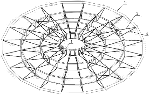
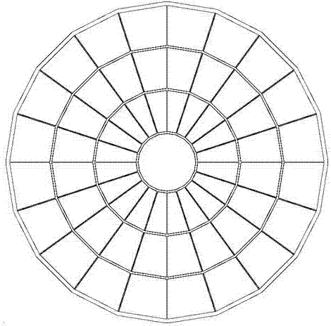
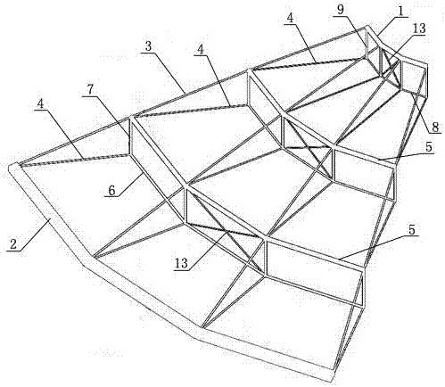
[0023] Such as figure 1 , 2 As shown in and 3, a rigid roof cable dome structure with hoop support includes an inner pull ring 1 and an outer ring 2, and the outer fulcrum of the outer ring 2 adopts the structural form of a pressure ring to form a self-balancing system. At least one ring of hoop components is arranged between the inner pull ring 1 and the outer ring 2, and the hoop component divides the inner pull ring 1 and the outer ring 2 into at least two stages of structure. 1 an...


PUM


Abstract

The invention discloses a rigid roof cable-dome structure with a circumferential-direction support. The rigid roof cable-dome structure comprises an internal pull ring and an external ring, at least one round of circumferential-direction assembly is arranged between the internal pull ring and the external ring, and the circumferential-direction assembly separates the part between the internal pull ring and the external ring into at least two stages of structures; a plurality of ridge cables arranged in a radial shape in the radial direction are arranged between the internal pull ring and the external ring, one ends of the ridge cables are connected with the internal pull ring, the other ends of the ridge cables are connected with supporting points of the external ring, and the middle of each ridge cable is connected with the upper end portion of the corresponding circumferential-direction assembly; and oblique cables are arranged between the circumferential-direction assembly and the external ring as well as between the circumferential-direction assembly and the internal pull ring correspondingly, if multiple rounds of circumferential-direction assemblies are arranged, oblique cables are arranged between the every two adjacent circumferential-direction assemblies, and the oblique cables are arranged in a radial shape in the radial direction. According to the rigid roof cable-dome structure with the circumferential-direction support, force transferring is direct, the high-strength character of an inhaul cable is brought into full play, the rigid roof cable-dome structure has the advantages of being good in rigidity, good in stability, simple in structure, rapid in construction and the like, meanwhile a rigid roof technology adopted by the rigid roof cable-dome structure is mature, and the cost is relatively low.

Description

technical field [0001] The invention belongs to the technical field of construction engineering, and in particular relates to a rigid roof cable dome structure with hoop support that can be applied to large-span buildings such as gymnasiums and exhibition halls. Background technique [0002] The cable dome structure is a tension structure proposed by American engineer Geiger based on Fuller's tension overall structure idea. As early as the 1940s, Fuller believed that the operation of the universe was carried out according to the principle of tensegrity, so he imagined that a truly efficient structural system should be a self-balancing system of pressure and tension. In 1984, his student, the sculptor Snelson, completed the first tensegrity model, based on which he designed urban sculptures, which proved Fuller's vision and was recognized as a starting point for the development of modern tensegrity structures. Fuller was more encouraged and inspired by this, and published th...

Claims


Application Information

Patent Timeline
IPC IPC(8): E04B1/32E04B7/08E04G21/12
CPCE04B1/3211E04B7/08E04G21/12E04B2001/3247E04B2001/3229E04G2021/127
Inventor 冯远向新岸邱添张旭东魏忠周魁政
Owner CHINA SOUTHWEST ARCHITECTURAL DESIGN & RES INST CORP LTD
Learn More