Underwater light source device with hairbrush and diaphragm

A technology of underwater light source and diaphragm, applied in the direction of gas/waterproof device, light source, electric light source, etc., can solve the problems of wasting time, test error, unable to be timely, etc., to improve experimental efficiency, experimental process safety, time saving effect

Inactive Publication Date: 2017-10-20
ZHEJIANG UNIV +2
View PDF5 Cites 1 Cited by
  • Summary
  • Abstract
  • Description
  • Claims
  • Application Information

AI Technical Summary

Problems solved by technology

[0002] When scientific researchers do underwater optical experiments, they often need to measure the background light when there is no light and the experimental data when there is light. However, it takes a certain time for a high-power light source to reach a stable working state when working underwater. Choosing to turn on and off the light source from time to time will not only waste time and reduce efficiency, but also cause unstable working conditions of the light source and bring experimental errors; when working underwater, water droplets or floating objects often adhere to the lamp wall, which will also cause It is very inconvenient to take out the underwater light source and clean it on the water surface due to the change of the light source and illumination conditions, and it cannot be done in time
[0003] So far, there is no underwater high-power light source with a brush and diaphragm that can clean up the lamp wall attachment in time and measure the background light when the light source is turned on.

Method used


Image

  • Underwater light source device with hairbrush and diaphragm
  • Underwater light source device with hairbrush and diaphragm
  • Underwater light source device with hairbrush and diaphragm

Examples


Embodiment Construction

[0017] The specific embodiments of the present invention will be further described below in conjunction with the accompanying drawings.

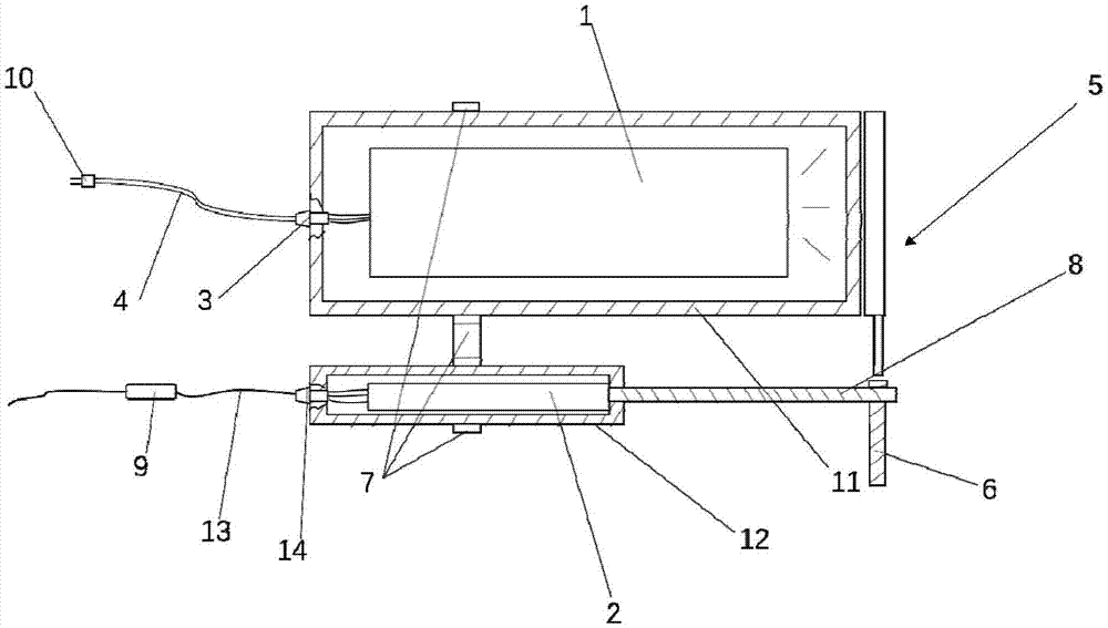
[0018] Such as Figure 1-3 As shown, the present invention provides an underwater light source device with a brush and a diaphragm, including a light source 1, a stepping motor 2, a rotating shaft 8, a diaphragm system 5, a swing rod 6, and a hoop 7; The rotation of the rod 6 and the rotating shaft 8 drives the swing rod 6 to swing to control the opening and closing of the aperture system 5; the aperture system 5 is closely attached to the light source 1, and is used to control whether the light from the light source 1 passes or not, and to clean the surface of the light source.

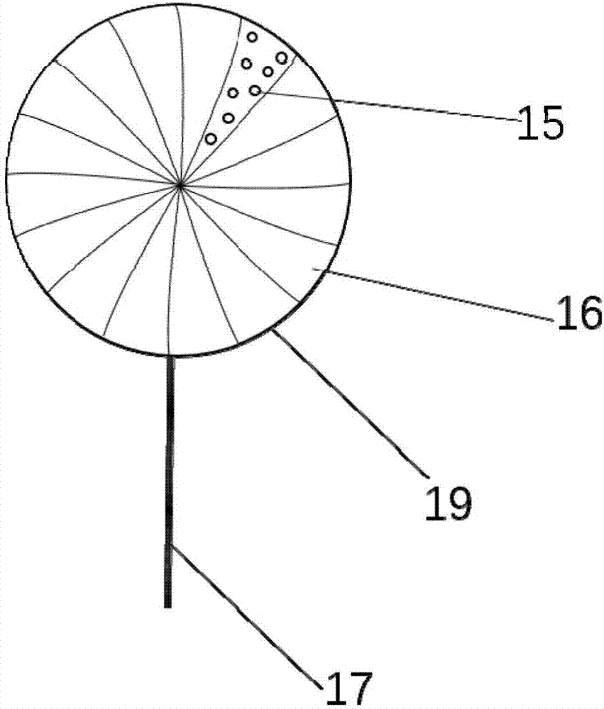
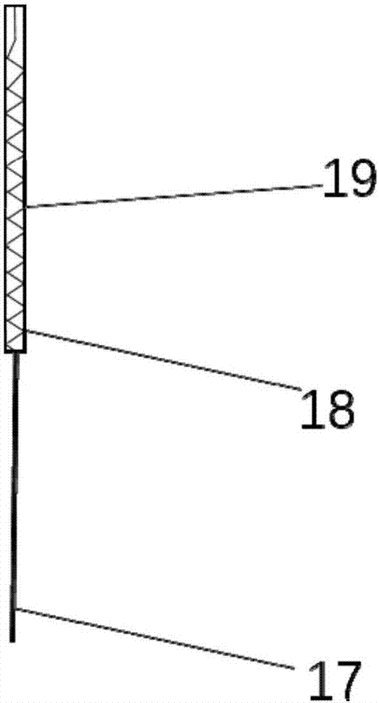
[0019] Such as Figure 2-3 As shown, the aperture system 5 includes an aperture, a brush 15 and a spring 18; the aperture in the present invention has the same structure as the existing aperture on the market, such as Nissin SK12, but not limited thereto, it has a...


PUM


Abstract

The invention discloses an underwater light source device with a hairbrush and a diaphragm for an underwater optical experiment with a light source. The underwater light source device comprises a light source, a stepping motor, a rotary shaft, a diaphragm system and an oscillating bar. The rotary shaft is connected to the output shaft of the stepping motor, the oscillating bar is arranged on the rotary shaft, and the rotary shaft rotates to drive the oscillating bar to control the diaphragm system to be turned on and off; the diaphragm system is attached to the light source for controlling illumination of the light source to pass through and to not pass through and clean the surface of the light source. The underwater light source device disclosed by the invention effectively avoids dangers due to instable working state as the light source is turned on and off when the power of the light source is relatively great (greater than 100W) and relatively large current on and off, the time required by waiting the working state of the light source to be stable is shortened, and the experimental efficiency is increased. Moreover, the surface of the light source is immediately cleaned to prevent attachments such as water drops and floats on the lamp wall from affecting illumination, so that the result obtained from the underwater experiment is more accurate and the experimental flow is safer.

Description

technical field [0001] The invention relates to underwater light source technology, in particular to an underwater light source device with a brush and a diaphragm. Background technique [0002] When scientific researchers do underwater optical experiments, they often need to measure the background light when there is no light and the experimental data when there is light. However, it takes a certain time for a high-power light source to reach a stable working state when working underwater. Choosing to turn on and off the light source from time to time will not only waste time and reduce efficiency, but also cause unstable working conditions of the light source and bring experimental errors; when working underwater, water droplets or floating objects often adhere to the lamp wall, which will also cause It is very inconvenient to take out the underwater light source to the water surface for cleaning due to the change of the light source illumination condition and cannot be do...

Claims


Application Information

Patent Timeline
Patent Type & Authority Applications(China)
IPC IPC(8): F21S2/00F21V1/00F21V33/00B08B1/00F21V31/00F21V23/00F21V14/08
CPCF21S2/00F21V1/00F21V14/08F21V23/002F21V31/005F21V33/00B08B1/12
Inventor 宋宏张峰郭乙陆魏贺陈瑶黄慧杨萍廖宁放
Owner ZHEJIANG UNIV
Why Eureka
Try Eureka