
PTC (Positive Temperature Coefficient) over-current protection component capable of eliminating accumulated heat influence

A technology of overcurrent protection components and heat, which is applied in the direction of electrical components, current response resistors, resistor components, etc., can solve problems such as packaging heat dissipation misoperation, line operation influence, etc., and achieve the effect of eliminating misoperation

Active Publication Date: 2017-10-20
上海萃励电子科技有限公司
View PDF7 Cites 2 Cited by
  • Summary
  • Abstract
  • Description
  • Claims
  • Application Information

AI Technical Summary

Problems solved by technology

In actual use, the accumulated heat generated by the small current in normal operation during the long-term use of PPTC components may cause malfunction due to poor heat dissipation of the package, which will affect the operation of the entire circuit

Method used


Image

  • PTC (Positive Temperature Coefficient) over-current protection component capable of eliminating accumulated heat influence

Examples


Embodiment 1

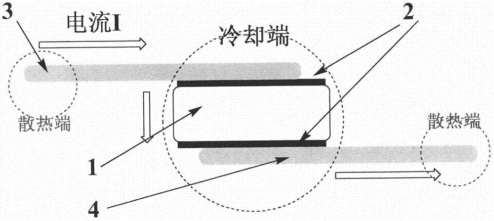
[0012] PTC overcurrent protection element that can eliminate the influence of accumulated heat, the structure is as figure 1 Shown: The PTC chip is a blended composite material of high-density polyethylene (HDPE) and Ni powder, the two sides of the PTC chip are covered with nickel-plated copper foil contact electrodes, and the N-type thermoelectric semiconductor Bi 2 Te 2.7 Se 0.3 and metal Ni electrodes are respectively welded on the nickel-plated copper foil on both sides. When working, the current flows from the N-type Bi 2 Te 2.7 Se 0.3 The pin flows in and flows out from the metal Ni pin, which plays a role in cooling the PTC chip.

Embodiment 2

[0014] PTC overcurrent protection element that can eliminate the influence of accumulated heat, the structure is as figure 1 Shown: The PTC chip is a blended composite material of high-density polyethylene (HDPE) and Ni powder. The two sides of the PTC chip are attached with metal Cu foil contact electrodes, metal Cu electrodes and P-type thermoelectric semiconductor Bi. 0.5 Sb 1.5 Te 3 The lead-out electrodes are respectively welded on the metal Cu electrodes on both sides. When working, the current flows from the metal Cu pin, from the P-type Bi 0.5 Sb 1.5 Te 3 The pins flow out to cool the PTC chip.

Embodiment 3

[0016] PTC overcurrent protection element that can eliminate the influence of accumulated heat, the structure is as figure 1 Shown: The PTC chip is a blended composite material of high-density polyethylene (HDPE) and Ni powder, the two sides of the PTC chip are attached with metal Ni foil contact electrodes, and the N-type thermoelectric semiconductor Bi 2 Te 2.7 Se 0.3 and P-type thermoelectric semiconductor Bi 0.5 Sb 1.5 Te 3 The lead-out electrodes are respectively welded on the metal Ni electrodes on both sides. When working, the current flows from the N-type Bi 2 Te 2.7 Se 0.3 pin inflow, from P-type Bi 0.5 Sb 1.5 Te 3 The pins flow out to cool the PTC chip.


PUM


Abstract

The invention discloses a PTC (Positive Temperature Coefficient) over-current protection component capable of eliminating accumulated heat influence. The PTC over-current protection component comprises a polymer-based PTC core layer, contact electrodes compounded on two sides of the core layer, and two conductive pins, wherein at least one of the two conductive pins is a thermoelectric semiconductor material; surface mount of the thermoelectric semiconductor pin has directionality; the thermoelectric semiconductor pin is mounted on one side on which current flows out; an N-type semiconductor is mounted on one side on which current flows in; one end, which is far away from the PTC chip, of the pin is radiated when the component works; and one end of the pin mounted on the chip electrode absorbs heat so as to achieve an effect of eliminating the PTC accumulated heat. Compared with the traditional PTC over-current protection component, the PTC over-current protection component disclosed by the invention has the advantages that the PTC chip is locally cooled in a low-current state by the two thermoelectric semiconductors, false operations caused by time accumulation joule heat are eliminated, and the component only performs over-current protection on transient joule heat generated by a high-current state.

Description

technical field [0001] The invention relates to a PTC overcurrent protection element capable of eliminating the influence of accumulated heat, and belongs to the technical field of electronic materials and elements. Background technique [0002] The resistivity of positive temperature coefficient (PCT) materials increases with the increase of temperature, and the composite material (PPTC) obtained by blending some polymers with conductive fillers has a lower room temperature resistivity, and the resistivity increases with temperature. Increase and sharply increase the resistance at a certain temperature point, which is used for recoverable fuses, that is, the resistance increases sharply in the state of high current to shut down the circuit, and it can recover by itself after troubleshooting. In actual use, the accumulated heat generated by the small current of normal work during the long-term use of PPTC components may cause malfunction due to poor heat dissipation of the p...

Claims


Application Information

Patent Timeline
IPC IPC(8): H01C1/084H01C1/14H01C7/02H01C7/13C08L23/06C08L27/16C08K3/08C08K3/04
CPCC08K3/04C08K3/08C08K2003/0862C08K2201/001H01C1/084H01C1/14H01C7/027H01C7/13C08L23/06C08L27/16
Inventor 汪元元
Owner 上海萃励电子科技有限公司
Learn More