Urination control instrument for urethra

A technology of urethra and urinal, applied in medical science, prosthesis, anti-incontinence device, etc., to achieve the effect of large urine flow, large valve opening and smooth urination

Active Publication Date: 2017-10-24
SECOND MILITARY MEDICAL UNIV OF THE PEOPLES LIBERATION ARMY
View PDF15 Cites 4 Cited by
  • Summary
  • Abstract
  • Description
  • Claims
  • Application Information

AI Technical Summary

Problems solved by technology

[0006] Therefore, in view of the technical problems that the urinary control device in the prior art cannot simultaneously meet the requirements of simple structure, convenient operation, smooth urination, high reliability, and no risk of infection, the purpose of the present invention is to provide a urethra that can simultaneously meet the above requirements. Containment device

Method used


Image

  • Urination control instrument for urethra
  • Urination control instrument for urethra
  • Urination control instrument for urethra

Examples


Embodiment 1

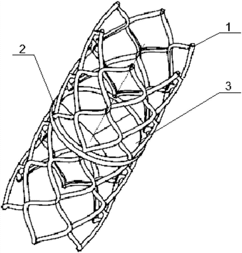
[0053] figure 1 Shown is a urethral urinary control device in a preferred embodiment of the present invention, which includes a urethral support 1 , a connecting ring 2 and a urethral valve 3 .

[0054] Urethral stent 1 is a mesh tube that can be implanted into the urethra. It is braided by nickel-titanium memory alloy. It is soft at low temperature and can be squeezed into a rope shape. The shape is restored in situ, and the positioning is accurate.

[0055] The connecting ring 2 is laterally fixed on the tube wall of the middle section of the urethral stent 1 and is integrated with the urethral stent 1 .

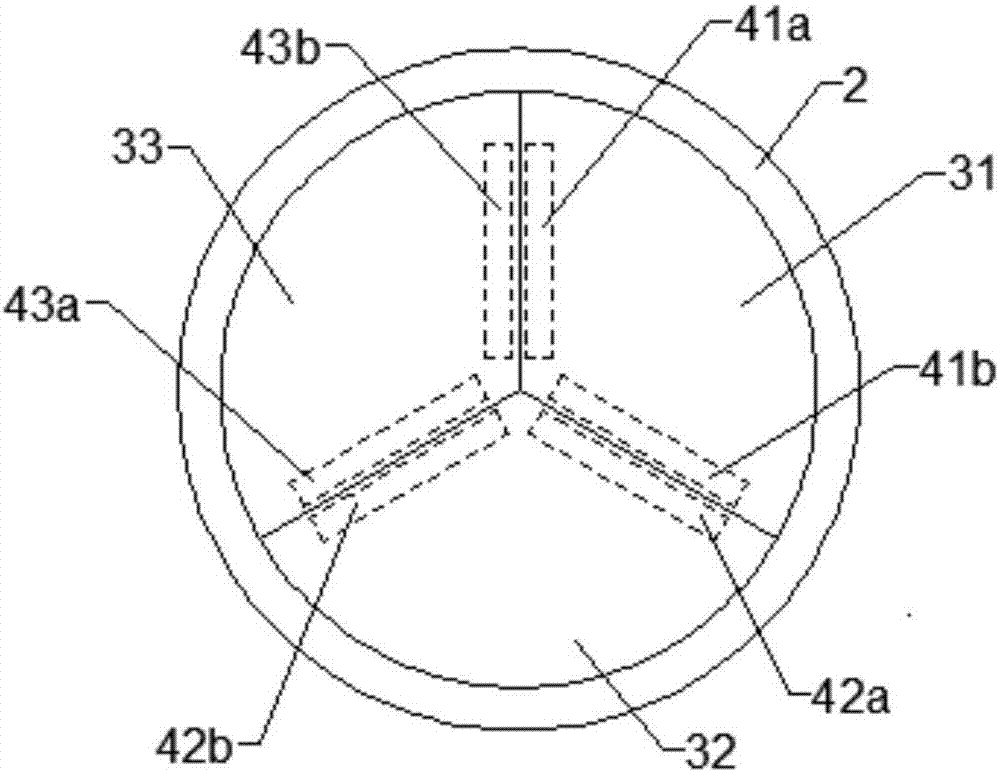
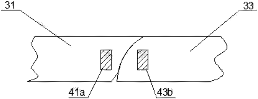
[0056] The urethral valve 3 is composed of three fan-shaped leaflets 31, 32 and 33 that can swing, and the arc edges of the fan-shaped leaflets 31, 32 and 33 are seamlessly fixedly connected with the connecting ring 2, as figure 2 Shown, the sides (straight line sides) that fan-shaped leaflets 31, 32 and 33 are connected to each other are as image 3 As shown, they are...

Embodiment 2

[0061] Figure 10 Shown is the urethral urinary control device of another preferred embodiment of the present invention, which is different from Embodiment 1 in that the urethral valve 3 is formed by a circular leaflet 34, such as Figure 11 As shown, two opposite points 34a on the periphery of the circular leaflet 34 are fixedly connected to the connecting ring 2, and the rest of the periphery of the circular leaflet 34 except the two fixedly connected points 34a is combined with the connecting ring 2 through the embedded magnet 4 In movable connection, when there is no external magnetic field, the periphery of the circular valve leaflet 34 and the connecting ring 2 are seamlessly connected to form a closure through the mutual attraction of the magnet assembly 4 . Under the action of an external magnetic field, both sides of the circular valve leaflet 34 are opened downwards, as Figure 12 shown.

Embodiment 3

[0063] Figure 13 Shown is another preferred embodiment of the urethral urinary control device of the present invention. Compared with Embodiment 1, the connecting frame 5 is also connected to the connecting ring 2. The connecting ring 2 and the connecting frame 5 form a connecting piece, and the connecting frame 5 is in the shape of Scattering divides the connection ring 2 into 3 fan-shaped areas, such as Figure 14 shown. The urethral valve 3 is composed of three swingable fan-shaped leaflets corresponding to the fan-shaped area. The arc-shaped edges of each fan-shaped leaflet are seamlessly and fixedly connected with the connecting ring 2, and the side edges of each fan-shaped leaflet are connected with the connecting frame 5. The magnet assembly 4 that can attract each other is also embedded inside the side edges of the adjacent fan-shaped leaflets.

[0064] Wherein, the leaflets of the urethral valve 3 can also be adjusted to 2 pieces, 4 pieces or more, and the shape of...


PUM


Abstract

The invention discloses an urination control instrument for the urethra. The instrument comprises a urethral stent which is netlike tube, a connecting piece comprising a connecting ring and a urethral valve. The urethral valve is connected with the connecting ring to form a valve capable of controlling a longitudinal channel of the urethral stent to open and close. The urethral valve comprises at least one valve leaflet, and at least one of the valve leaflets can be opened in a swing manner. Magnet combinations attracting each other are embedded inside the edge of the swingable valve leaflet and the connecting piece movably connected with the same and / or inside the adjacent valve leaflet. The urethral stent is of a netlike structure and is in line contact with the urethra after being implanted to the urethra, stimulation to the urethra is reduced, occurrence of corresponding complications is reduced, and comfortableness of the implanted urethra is improved. The valve leaflets are controlled to swing by controlling the magnet combinations, further the valve leaflets are controlled to open and close, controllability in urination is realized, the valve orifice is large when the valve leaflets are opened to make urination smooth.

Description

technical field [0001] The invention belongs to the technical field of medical devices, and in particular relates to a urethral urinary control device. Background technique [0002] Urinary incontinence is the loss of self-control of urination due to urethral sphincter damage or nerve dysfunction, making urine flow out involuntarily. Urinary incontinence is a relatively common disease of the human urinary system. There are many causes, often caused by congenital or acquired brain and spinal cord lesions, trauma, prostate surgery, urethral stricture repair, etc. It not only causes inconvenience and pain to the patient's life, but also may cause serious complications and even endanger the patient's life. Placement of artificial urinary sphincter is currently one of the main methods that can fundamentally solve the problem of urinary incontinence, but the artificial urinary sphincter that has been clinically used in the world requires surgical implantation. On the one hand, ...

Claims


Application Information

Patent Timeline
Patent Type & Authority Applications(China)
IPC IPC(8): A61F2/00
CPCA61F2/0018A61F2210/0014
Inventor 孙颖浩肖亮严新谊
Owner SECOND MILITARY MEDICAL UNIV OF THE PEOPLES LIBERATION ARMY
Why Eureka
Try Eureka