
Thrombolysis tube

A catheter and thrombolysis technology, applied in the field of medical equipment, can solve problems such as unsatisfactory thrombolysis effect, incomplete thrombolysis, and aggravation of disease.

Active Publication Date: 2017-10-24
南华大学附属第二医院
View PDF9 Cites 7 Cited by
  • Summary
  • Abstract
  • Description
  • Claims
  • Application Information

AI Technical Summary

Problems solved by technology

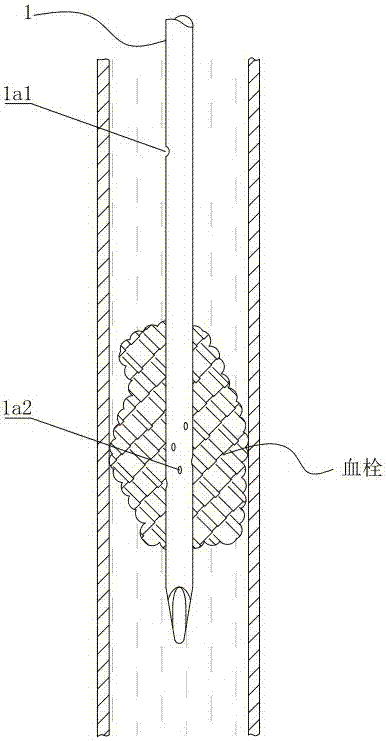
This type of thrombolytic catheter has the following problems: For the situation of a large amount of thrombus in the blood vessel, see figure 1 As shown, the gap between the thrombus can still allow blood to pass through, but after intubation, the catheter blocks the gap that originally allowed blood to pass through, which will aggravate the condition and even bring life-threatening to the patient
The thrombolysis catheter has the following defects in use: 1. There is only one outlet at the distal end of the thrombolysis chamber and it is located in front of the thrombus. Dilution in the blood, which will lead to low drug concentration in contact with the thrombus, and the thrombolytic effect is not ideal
2. The outlet of the thrombolysis chamber is located on one side of the perfusion chamber. Since the drug solution is sprayed from the outlet of the thrombolysis chamber and mixed with the blood to dilute, the concentration of the drug solution near the outlet of the thrombolysis chamber will be greater than that on the other side of the perfusion chamber. In theory, the thrombolysis speed on the side with a higher concentration of the drug solution will be greater than that on the side with a lower concentration of the drug solution. The drug will flow away from this pathway, which may lead to incomplete thrombolysis on the other side of the perfusion chamber (the side with low drug concentration)

Method used


Image

  • Thrombolysis tube
  • Thrombolysis tube
  • Thrombolysis tube

Examples


Embodiment Construction

[0034] In the description of the present invention, it should be understood that the orientation or positional relationship indicated by the terms "front", "rear", "inner", "outer" and the like are based on the orientation or positional relationship shown in the accompanying drawings, and are only for It is convenient to describe the present invention and simplify the description, but does not indicate or imply that the device or element referred to must have a specific orientation, be constructed and operate in a specific orientation, and thus should not be construed as limiting the present invention.

[0035] In addition, the terms "first" and "second" are used for descriptive purposes only, and cannot be interpreted as indicating or implying relative importance or implicitly specifying the quantity of indicated technical features. In the description of the present invention, "plurality" means two or more, unless otherwise specifically defined.

[0036] In order to facilitat...


PUM


Abstract

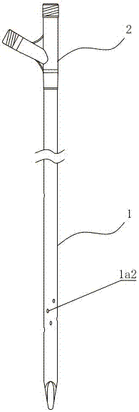
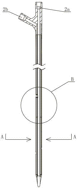
The invention discloses a thrombolysis tube, relating to the medical equipment technology field. The thrombolysis tube comprises a tube main body and a connector connected to the rear end of the tube body; the tube main body comprises an outer tube and an inner tube; the outer tube sleeves the inner tube; a drug filling cavity is a gap between the outer tube and the inner tube; a tube cavity of the inner tube is a drainage cavity; the drug filling cavity is isolated from the drainage cavity; the connector comprises a first port and a second port; the first port is communicated with the drainage cavity; the second port is communicated with the drug filling cavity; an opening is formed in the front end of the drainage cavity; the front end of the outer tube is welded together with the outer circumference surface of the inner tube so as to make the front end of the drug filling cavity sealed; a drainage hole which is used for guiding blood to the drainage cavity and a plurality of drug outlet holes communicating with the drug filling cavity are formed on the tube wall of the outer tube; the drainage hole is arranged behind the drug outlet holes; the drainage hole is communicated with the drainage cavity through the flow guiding tube; the flow guiding tube passes through the drug filling cavity and the two ends of the flow guiding tube are correspondingly connected to the drainage hole and the drainage cavity. The thrombolysis tube makes sure blood circulation is smooth and guarantees a good thrombolysis effect.

Description

technical field [0001] The invention relates to the technical field of medical equipment, in particular to a thrombolytic catheter. Background technique [0002] A thrombus is mainly composed of insoluble fibrin, deposited platelets, accumulated white blood cells, and trapped red blood cells. When the blood flows through the thrombus, it is hindered by the thrombus, and the local pressure of the blood vessel increases. If the thrombus is serious, it may even cause thrombotic occlusion, which endangers the life of the patient. [0003] At present, there are three commonly used clinical methods for treating thrombus. The first is artificial mechanical method, and the thrombus in the blood vessel is taken out by surgical operation or suction device. The second is to implant a stent to expand the lumen of the blood vessel. The third is thrombolytic drug therapy, which gradually dissolves the thrombus by injecting thrombolytic drugs to achieve the purpose of opening blood vesse...

Claims


Application Information

Patent Timeline
IPC IPC(8): A61M25/14A61B17/22
CPCA61M25/0023A61M25/0043A61M25/007A61B17/22012A61B2017/22084A61M2202/0413
Inventor 毕国善熊国祚宁丹
Owner 南华大学附属第二医院
Learn More