
Punching machine shearing photo-electric safety device

A technology for photoelectric protection and punching machines, which is applied in metal processing equipment, safety equipment, manufacturing tools, etc. It can solve problems such as the inability to reduce the vibration of photoelectric protectors, the inability to monitor the working conditions of punching machines, and the lack of monitoring cameras, etc., to achieve all-round protection. Personnel, improve protection efficiency, and facilitate the movement of the punching machine

Inactive Publication Date: 2017-10-24
FOSHAN SAIWEI PHOTOELECTRIC TECH CO LTD
View PDF5 Cites 3 Cited by
  • Summary
  • Abstract
  • Description
  • Claims
  • Application Information

AI Technical Summary

Problems solved by technology

[0004] The present invention provides a photoelectric protection device for punching and shearing machines, which can effectively solve the above-mentioned background technology that no shock absorbing plate and spring column are provided, the vibration generated when the photoelectric protector is working cannot be reduced, the protection efficiency cannot be improved, and no monitoring camera is installed. It is impossible to monitor the surrounding environment and the working conditions of the punch press when the photoelectric protector is working. There is no distance sensor, and the distance between the staff near the punch press and the punching plate cannot be detected, and the staff cannot be fully protected. There is no shock-absorbing wheel, and the punch press is inconvenient to move. , At the same time, it cannot reduce the vibration problem when the punch press is working

Method used


Image

  • Punching machine shearing photo-electric safety device
  • Punching machine shearing photo-electric safety device
  • Punching machine shearing photo-electric safety device

Examples


Embodiment Construction

[0022] The preferred embodiments of the present invention will be described below in conjunction with the accompanying drawings. It should be understood that the preferred embodiments described here are only used to illustrate and explain the present invention, and are not intended to limit the present invention.

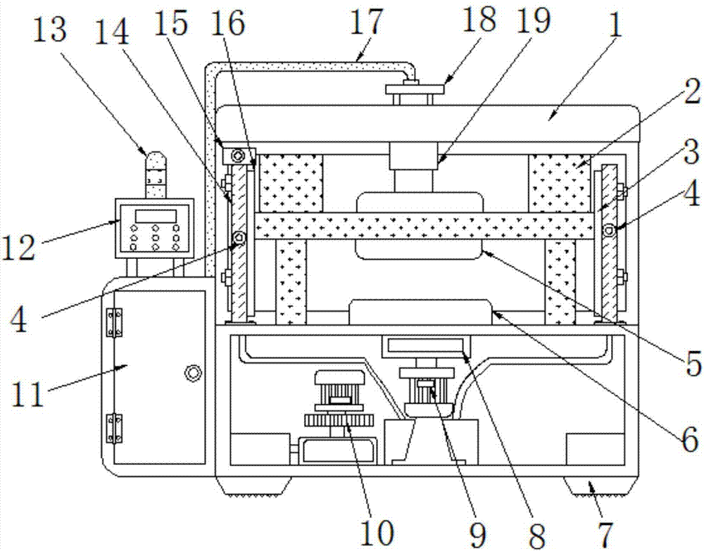
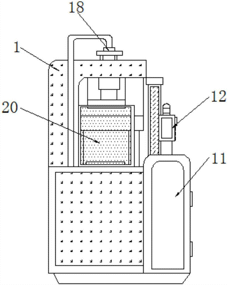
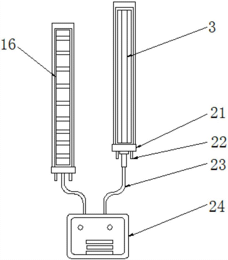
[0023] Example: such as Figure 1-4 As shown, the present invention provides a technical solution, a photoelectric protection device for punching and shearing machines, including a punching machine body 1, a guide rod 2, a light emitter 3, a distance sensor 4, a punching plate 5, a bearing plate 6, a supporting base 7, Reducer 8, servo motor 9, hydraulic pump 10, electric control box 11, control panel 12, alarm 13, mounting plate 14, monitoring camera 15, light receiver 16, oil pipeline 17, hydraulic cylinder 18, telescopic rod 19, baffle 20. Damping plate 21, spring column 22, transmission line 23, built-in controller 24 and damping wheel 25, the upper end of punch...


PUM


Abstract

The invention discloses a punching machine shearing photo-electric safety device which comprises a punching machine body, a light emitter, a transmission line, a built-in controller and damping wheels. A hydraulic cylinder is embedded into the upper end of the punching machine body. A supporting base plate is arranged at the lower end of the punching machine body. A hydraulic pump is arranged at the bottom of the punching machine body. An oil conveying pipe is connected to one end of the hydraulic cylinder. The punching machine shearing photo-electric safety device is scientific and reasonable in structure, and safe and convenient to use; by arranging a damping plate and a spring pillar, vibration generated when a photo-electric protector works can be reduced, and the protecting efficiency of the photo-electric protector can be improved; by arranging a surveillance camera, the surroundings and the punching machine working condition are monitored when the photo-electric protector works, and a manager can manage the device more conveniently; by arranging a distance sensor, the distance between a punching plate and a worker near the punching machine can be detected, comprehensive worker protection can be achieved, due to the design, operation is convenient, the safety coefficient is high, and the working efficiency is indirectly improved.

Description

technical field [0001] The invention relates to the technical field of photoelectric protection devices for punching and shearing machines, in particular to a photoelectric protection device for punching and shearing machines. Background technique [0002] Safety light curtains are also known as safety photoelectric, safety grating, photoelectric protector, etc., mainly used in machining, automation and other industries, correctly installed in punch presses, presses, injection molding machines, robotic arms, paper cutting machinery, automation equipment, packaging Dangerous work areas such as equipment can effectively protect the personal safety of the operator. The photoelectric protector is generally composed of sensors, controllers, transmission lines and mounting brackets. The sensor is composed of a light emitter and a light receiver. , the light receiver receives the corresponding light beam, and a rectangular protection area is formed between the light emitter and the...

Claims


Application Information

Patent Timeline
Patent Type & Authority Applications(China)
IPC IPC(8): B21D55/00
CPCB21D55/00
Inventor 傅飞艳
Owner FOSHAN SAIWEI PHOTOELECTRIC TECH CO LTD
Learn More