
Cutting device for vehicle rubber pipe production

A cutting device and rubber tube technology, applied in metal processing and other directions, can solve the problems that the tube material cannot meet the production requirements, the cutting length of the tube material cannot be positioned, and the heat dissipation of the cutting head is not set, so as to achieve simple structure and strong practicability , the effect of easy operation

Inactive Publication Date: 2017-10-24
枞阳县金源汽车零部件有限公司
View PDF9 Cites 9 Cited by
  • Summary
  • Abstract
  • Description
  • Claims
  • Application Information

AI Technical Summary

Problems solved by technology

[0002] The rubber tube has good physiological inertia, UV resistance, ozone resistance, high and low temperature resistance, high transparency, strong resilience, compression resistance, permanent deformation, oil resistance, stamping resistance, acid and alkali resistance, wear resistance, flame retardant, voltage resistance, Conductivity and other properties are widely used in automobiles. In the production process of automobile rubber pipe fittings, the rubber pipe fittings will be cut into short pipes of different lengths according to the production needs. The traditional rubber pipe cutting device cannot position the cutting of the pipe material The length and cutting accuracy are poor, and the cut pipe material cannot meet the production requirements. Moreover, the traditional rubber pipe cutting device will generate a lot of dust during the cutting process, polluting the environment, and there is no cooling device for the cutting head. device, the cutting head will affect the cutting effect due to overheating during the long-term cutting process

Method used


Image

  • Cutting device for vehicle rubber pipe production
  • Cutting device for vehicle rubber pipe production
  • Cutting device for vehicle rubber pipe production

Examples


Embodiment Construction

[0017] The following will clearly and completely describe the technical solutions in the embodiments of the present invention with reference to the accompanying drawings in the embodiments of the present invention. Obviously, the described embodiments are only some, not all, embodiments of the present invention. Based on the embodiments of the present invention, all other embodiments obtained by persons of ordinary skill in the art without making creative efforts belong to the protection scope of the present invention.

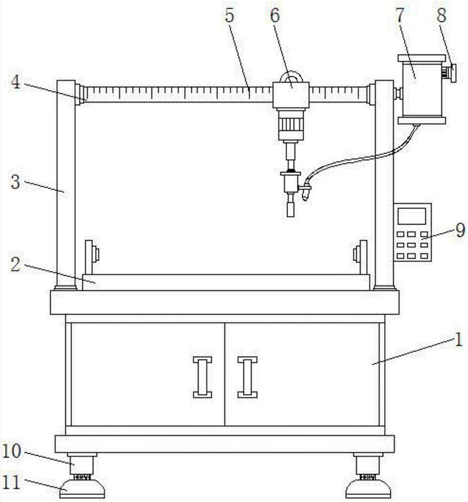
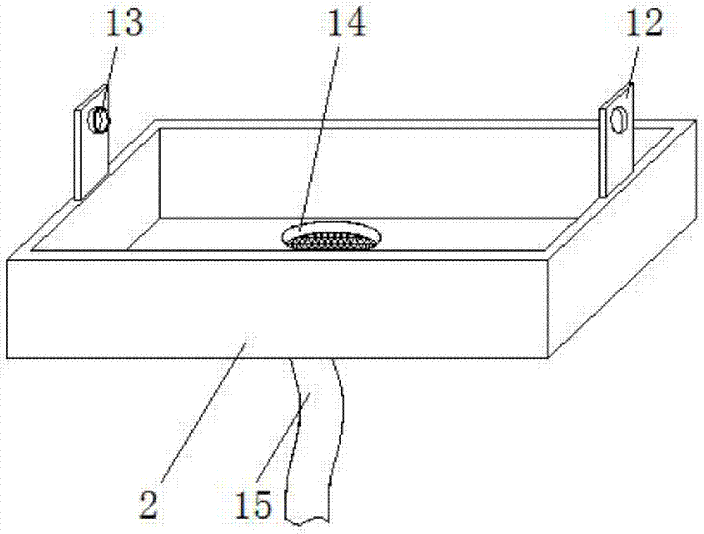
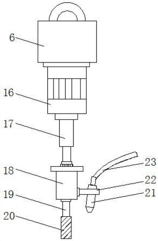
[0018] see Figure 1-4 , in the embodiment of the present invention, a kind of cutting device for automobile rubber tube production, comprises machine body 1 and frame 3, and the top of frame 3 is horizontally provided with slide rail 4, slide block 6 is installed on the slide rail 4, slide block The bottom of 6 is equipped with hydraulic cylinder 16, and the bottom end of hydraulic cylinder 16 is connected with rotating motor 18 by piston rod 17, and the bott...


PUM


Abstract

The invention discloses a cutting device for the production of automobile rubber tubes, which comprises a machine body and a frame. A sliding track is horizontally arranged on the top of the frame, and a sliding block is slidably installed on the sliding track. There is a hydraulic cylinder, the bottom end of the hydraulic cylinder is connected with the rotary motor through the piston rod, the bottom end of the rotary motor is connected with the cutting head through the rotating shaft, and a cooling liquid nozzle is arranged on one side of the cutting head, so A coolant tank is installed on the top of one side of the frame, and a cutting groove is arranged on the top of the body. The invention can realize the precise cutting of the pipe material, and the cutting effect is good. Through the cooling liquid nozzle provided on one side of the cutting head, the heat dissipation function of the cutting head can be realized, so as to avoid the overheating of the cutting head after working for a long time. Cutting effect, can reduce the dust generated in the cutting process, reduce pollution, and simple structure, easy to use, strong practicability.

Description

technical field [0001] The invention relates to the technical field of automobile plastic production equipment, in particular to a cutting device for automobile rubber tube production. Background technique [0002] The rubber tube has good physiological inertia, UV resistance, ozone resistance, high and low temperature resistance, high transparency, strong resilience, compression resistance, permanent deformation, oil resistance, stamping resistance, acid and alkali resistance, wear resistance, flame retardant, voltage resistance, Conductivity and other properties are widely used in automobiles. In the production process of automobile rubber pipe fittings, the rubber pipe fittings will be cut into short pipes of different lengths according to the production needs. The traditional rubber pipe cutting device cannot position the cutting of the pipe material The length and cutting accuracy are poor, and the cut pipe material cannot meet the production requirements. Moreover, the...

Claims


Application Information

Patent Timeline
Patent Type & Authority Applications(China)
IPC IPC(8): B26D1/12B26D7/08B26D7/26B26D7/28
CPCB26D1/12B26D7/08B26D7/2628B26D7/28B26D2007/2657
Inventor 周留芳
Owner 枞阳县金源汽车零部件有限公司
Learn More