Inner stress reducing die injection molding technology and die

An internal stress and mold technology, applied in the field of mold and mold injection, can solve problems such as difficulty in meeting people's production requirements, large internal stress of finished products, complex process steps, etc. simple steps

Inactive Publication Date: 2017-10-24
滁州市博康模具塑料有限公司
View PDF0 Cites 0 Cited by
  • Summary
  • Abstract
  • Description
  • Claims
  • Application Information

AI Technical Summary

Problems solved by technology

There are still certain defects in the implementation process of the mold injection molding process in the prior art, such as complex process steps, long cycle time, and high cost. Meet people's requirements for production

Method used


Image

  • Inner stress reducing die injection molding technology and die
  • Inner stress reducing die injection molding technology and die

Examples


specific Embodiment 1

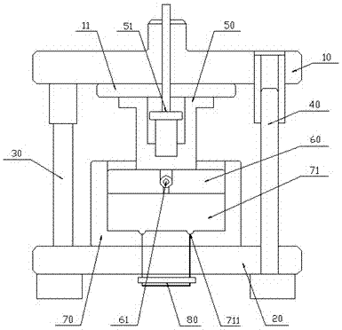
[0028] Such as figure 1 As shown, a mold for reducing internal stress according to this embodiment includes: an upper mold base 10 and a lower mold base 20. A hydraulic rod 30 is provided between the upper mold base 10 and the lower mold base 20 and used in conjunction with each other. A connecting template 11 is provided below the upper mold base 10, a mold gate 50 is provided below the connecting template 11, a movable mold 60 is provided below the mold gate 50, and the lower mold seat 20 A forming mold 70 used in cooperation with the movable mold 60 is provided thereon. The forming mold 70 is provided with a cavity 71, and the movable mold 60 is movably arranged in the cavity 71.

[0029] In a further improvement, the mold gate 50 is also provided with an elastic material device 51, the movable mold 60 is provided with an extrusion nozzle 61 for use with the mold gate 50, and the cavity 71 is provided with an overflow port 711 and the storage hopper 80 used with the overflow o...

specific Embodiment 2

[0047] Such as figure 1 As shown, a mold for reducing internal stress according to this embodiment includes: an upper mold base 10 and a lower mold base 20. A hydraulic rod 30 is provided between the upper mold base 10 and the lower mold base 20 and used in conjunction with each other. A connecting template 11 is provided below the upper mold base 10, a mold gate 50 is provided below the connecting template 11, a movable mold 60 is provided below the mold gate 50, and the lower mold seat 20 A forming mold 70 used in cooperation with the movable mold 60 is provided thereon. The forming mold 70 is provided with a cavity 71, and the movable mold 60 is movably arranged in the cavity 71.

[0048] In a further improvement, the mold gate 50 is also provided with an elastic material device 51, the movable mold 60 is provided with an extrusion nozzle 61 for use with the mold gate 50, and the cavity 71 is provided with an overflow port 711 and the storage hopper 80 used with the overflow o...

specific Embodiment 3

[0066] Such as figure 1 As shown, a mold for reducing internal stress according to this embodiment includes: an upper mold base 10 and a lower mold base 20. A hydraulic rod 30 is provided between the upper mold base 10 and the lower mold base 20 and used in conjunction with each other. A connecting template 11 is provided below the upper mold base 10, a mold gate 50 is provided below the connecting template 11, a movable mold 60 is provided below the mold gate 50, and the lower mold seat 20 A forming mold 70 used in cooperation with the movable mold 60 is provided thereon. The forming mold 70 is provided with a cavity 71, and the movable mold 60 is movably arranged in the cavity 71.

[0067] In a further improvement, the mold gate 50 is also provided with an elastic material device 51, the movable mold 60 is provided with an extrusion nozzle 61 for use with the mold gate 50, and the cavity 71 is provided with an overflow port 711 and the storage hopper 80 used with the overflow o...


PUM


Abstract

The invention discloses a mold for reducing internal stress, comprising: an upper mold base and a lower mold base, a hydraulic rod and a piston rod used in conjunction are arranged between the upper mold base and the lower mold base, and the upper mold base A connecting template is arranged under the seat, a mold gate is arranged under the connecting template, a movable mold is arranged under the mold gate, a forming mold used in conjunction with the movable mold is arranged on the lower mold base, and the molding A mold cavity is arranged on the mold, and the movable mold is movably arranged in the mold cavity. The invention eliminates the internal stress existing in the injection molded parts, so that the quality of the injection molded parts is high, and the production efficiency and yield of the mold are greatly improved.

Description

Technical field [0001] The invention relates to a mold injection process and a mold for reducing internal stress, and belongs to the technical field of molds and mold injection molding. Background technique [0002] Injection mold is a tool for producing plastic products, as well as a tool for giving plastic products a complete structure and precise dimensions. Injection molding is a processing method used in the mass production of certain complex-shaped parts. Specifically, it refers to the high-pressure injection of heated plastic into the mold cavity by an injection molding machine, and the molded product is obtained after cooling and solidification. Injection molds are divided into thermosetting plastic molds and thermoplastic plastic molds according to the molding characteristics; according to the molding process, they are divided into transfer molds, blow molds, casting molds, thermoforming molds, hot press molds (compression molds), injection molds, etc. Among them, hot p...

Claims


Application Information

Patent Timeline
Patent Type & Authority Applications(China)
IPC IPC(8): B29C45/26B29C45/17B29C45/73B29C45/76
CPCB29C45/26B29C45/0025B29C45/1706B29C45/7312B29C45/76B29C2045/0027B29C2945/76551B29C2945/76732B29C2945/76775
Inventor 田敬松
Owner 滁州市博康模具塑料有限公司
Why Eureka
Try Eureka