One-person-operable power line paving device

A power line and wire laying technology, which is applied in the direction of conveying filamentous materials, thin material processing, transportation and packaging, etc., can solve problems such as physical exertion, excessive tension of wires, and influence on line transmission safety

Inactive Publication Date: 2017-10-24
STATE GRID SHANDONG ELECTRIC POWER COMPANY WEIFANG POWER SUPPLY +1
View PDF0 Cites 0 Cited by
  • Summary
  • Abstract
  • Description
  • Claims
  • Application Information

AI Technical Summary

Problems solved by technology

Therefore, after the wire tightening work is over, the staff has to use their shoulders to lift the wires out of the trolley, lift them up to the height of the insulator, and put them into the groove on the top of the insulator for binding. This requires a lot of physical strength and seriously affects the work. schedule
[0004] In the construction, the conductors with small diameters are relatively light, and the staff can complete the lifting and binding of the conductors without much effort. For the phase line, since the pay-off block must also be fixed on the lower cross arm, the distance from the insulator on the top of the pole is about 1100mm. The height distance is very large, and sometimes even two people are required to complete it, which will easily lead to slow construction progress and delay in power transmission time. status
The second disadvantage is that in order to reduce the difficulty of lifting the neutral phase line, the pay-off block is usually removed from the lower cross arm, and then fixed to the top cap of the neutral phase line for use. The problem caused by this is that it needs a second It is very inconvenient to disassemble and install the wire block
The third disadvantage is that after the wire is lifted to a higher insulator, the tension of ...

Method used


Image

  • One-person-operable power line paving device
  • One-person-operable power line paving device
  • One-person-operable power line paving device

Examples


Embodiment Construction

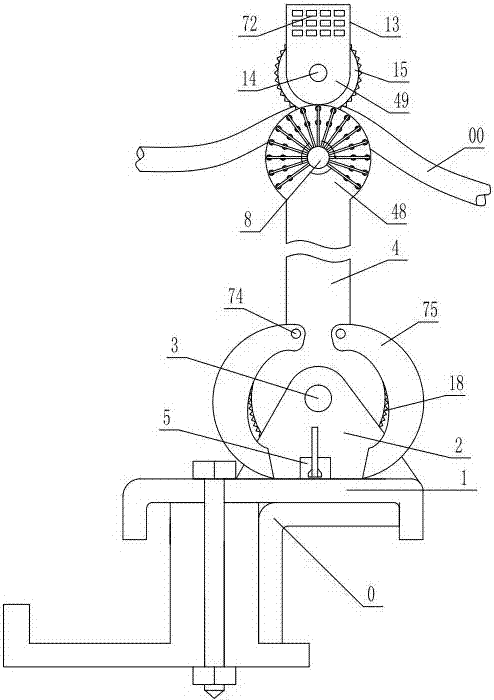
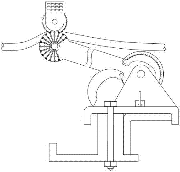
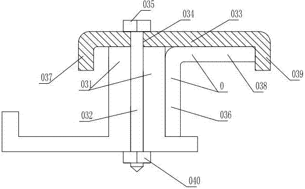
[0030]As shown in the figure, the power line laying device that can be operated by one person includes a base 1, and the bottom of the base is provided with a lower locking device that is locked and matched with the cross arm 0 of the pole. The positioning plate 031 at the bottom, the positioning plate 031 is provided with an axially horizontally extending inner screw hole 032, and also includes a clamping plate 033, the upper part of the clamping plate 033 is provided with a clamping hole 034, and the clamping hole 034 is inserted with a The inner screw hole 032 is screw-connected with the clamping bolt 035, the upper end of the clamping plate 033 is fixed with the upper hook plate 037 which is hooked and matched with the horizontal plate 036 of the cross arm 0, and the lower end of the clamping plate 033 is fixed with a hook plate 037 which is connected with the cross arm 030. The vertical plate 038 is hooked with the lower hook plate 039, and the end of the clamping bolt 035...


PUM


Abstract

The invention discloses a power line laying device operable by one person, which comprises a base, the bottom of the base is provided with a lower locking device for locking and cooperating with the pole cross-arm, the base is fixed with a bracket, and the bracket is hinged through the bracket shaft. Supporting cylinder, the supporting cylinder is provided with a lower positioning device for matching the positioning of the supporting cylinder. The upper end of the supporting cylinder is equipped with an upper gear that rotates close to the outer surface of the main support plate through a rotating connection device. Cooperating with the upper positioning device, the upper part of the upper gear is hinged with an upper bracket, and an upper locking device is arranged between the auxiliary support plate and the upper bracket. The advantage is that it is easy to install, reliable to fix, and easy to disassemble. It can freely adjust the pay-off height according to the actual height of the pole insulator, and can automatically determine the length of the pay-off cable. It only needs to be installed and disassembled once when the wire is set up. After the wire tightening operation, it only needs to translate the wire. Yes, the tightness of the wires before and after the tightening is consistent to ensure the quality, and one person can operate it.

Description

technical field [0001] The invention relates to a power line laying device operable by one person. Background technique [0002] The pay-off block is a tool that must be used in the construction of power lines. The main structure is composed of aluminum or nylon pulleys, frame fixing devices, hooks or U-shaped groove stabilizing devices. Using the pulley during the line erection and tensioning process can reduce the wire Excellent frictional resistance, prevent wire strand damage and insulation layer damage, and can increase construction speed and reduce power outage time. [0003] Now in the construction of 10kV and below power lines, the distance between the U-shaped groove stabilizer and the top of the pulley is about 140mm for the pay-off tackle used, while the height of the P-15 rod insulator is about 240mm, and the height of the P-20 rod insulator is about 140mm. The height of the insulator is about 350mm, the pulley is short, the insulator is high, and the gap is lar...

Claims


Application Information

Patent Timeline
IPC IPC(8): B65H57/14B65H57/26
CPCB65H57/14B65H57/26B65H2701/34
Inventor 李玉亮胡忠彦陈婧王立勇曲万红葛峰袁之军范蓁蓁孟庆江玄其斌陈洪正徐业堂李国华肖全成夏建委
Owner STATE GRID SHANDONG ELECTRIC POWER COMPANY WEIFANG POWER SUPPLY
Why Eureka
Try Eureka