

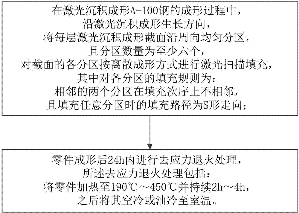
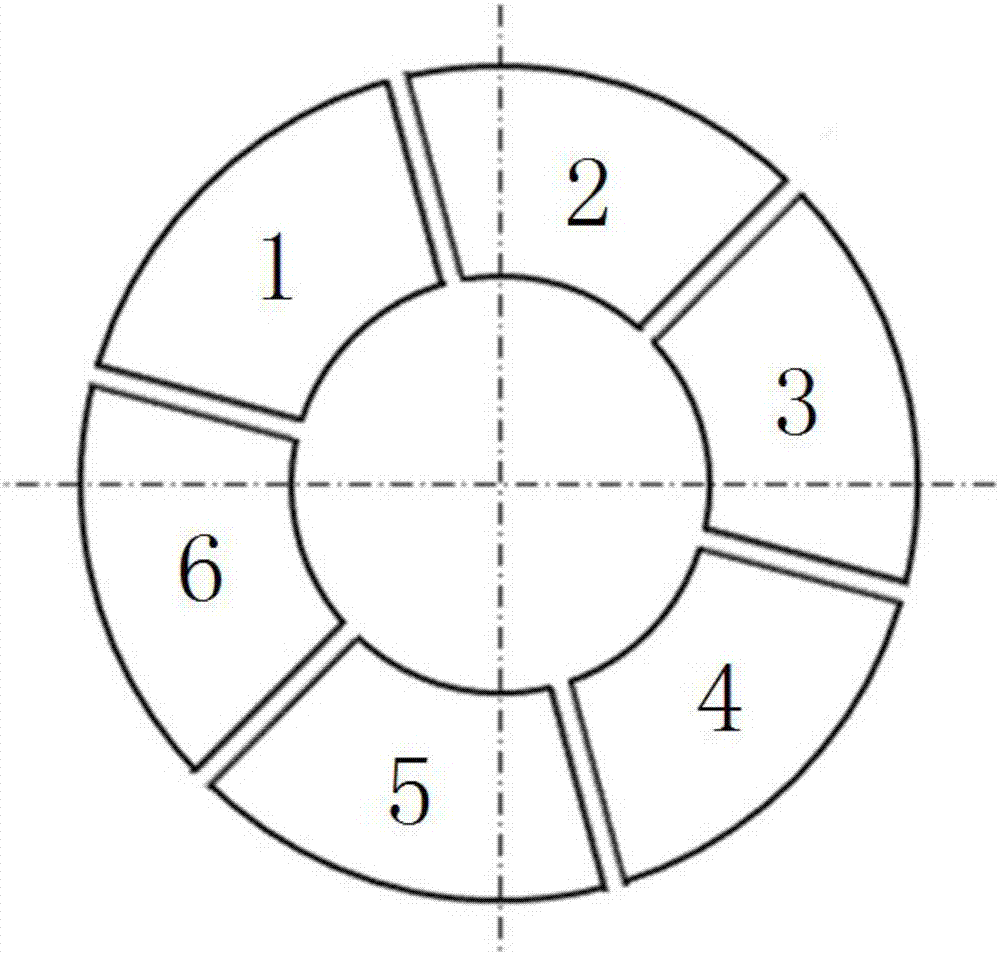
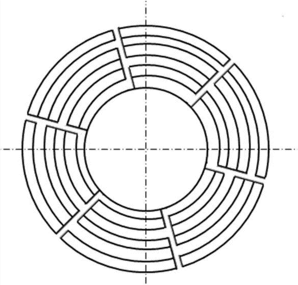
Method for preventing deformation cracking of laser deposition formed A-100 steel structure
A laser deposition and steel structure technology, applied in the direction of process efficiency improvement, additive manufacturing, coating, etc., can solve the problems of large cooling shrinkage, increased cracking tendency, large thermal expansion coefficient, etc., to prevent deformation cracking and reduce thermal stress The effect produced
- Summary
- Abstract
- Description
- Claims
- Application Information
AI Technical Summary
Problems solved by technology
Method used
Image

Examples
Embodiment Construction
[0012] In order to make the objectives, technical solutions and advantages of the present invention clearer, the technical solutions in the embodiments of the present invention will be described in more detail below in conjunction with the drawings in the embodiments of the present invention.
[0013] It should be noted that the embodiments described below with reference to the accompanying drawings are exemplary and intended to explain the present invention, but should not be construed as limiting the present invention. In the drawings, the same or similar reference numerals denote the same or similar elements or elements having the same or similar functions throughout. The described embodiments are part of the embodiments of the present invention, but not all of the embodiments. In the case of no conflict, the embodiments in the present application and the features in the embodiments can be combined with each other. Based on the embodiments of the present invention, all othe...
PUM
 Abstract
Description
Claims
Application Information