

Split stator and manufacturing method thereof
- Summary
- Abstract
- Description
- Claims
- Application Information
AI Technical Summary
Benefits of technology
Problems solved by technology
Method used
Image

Examples
first embodiment
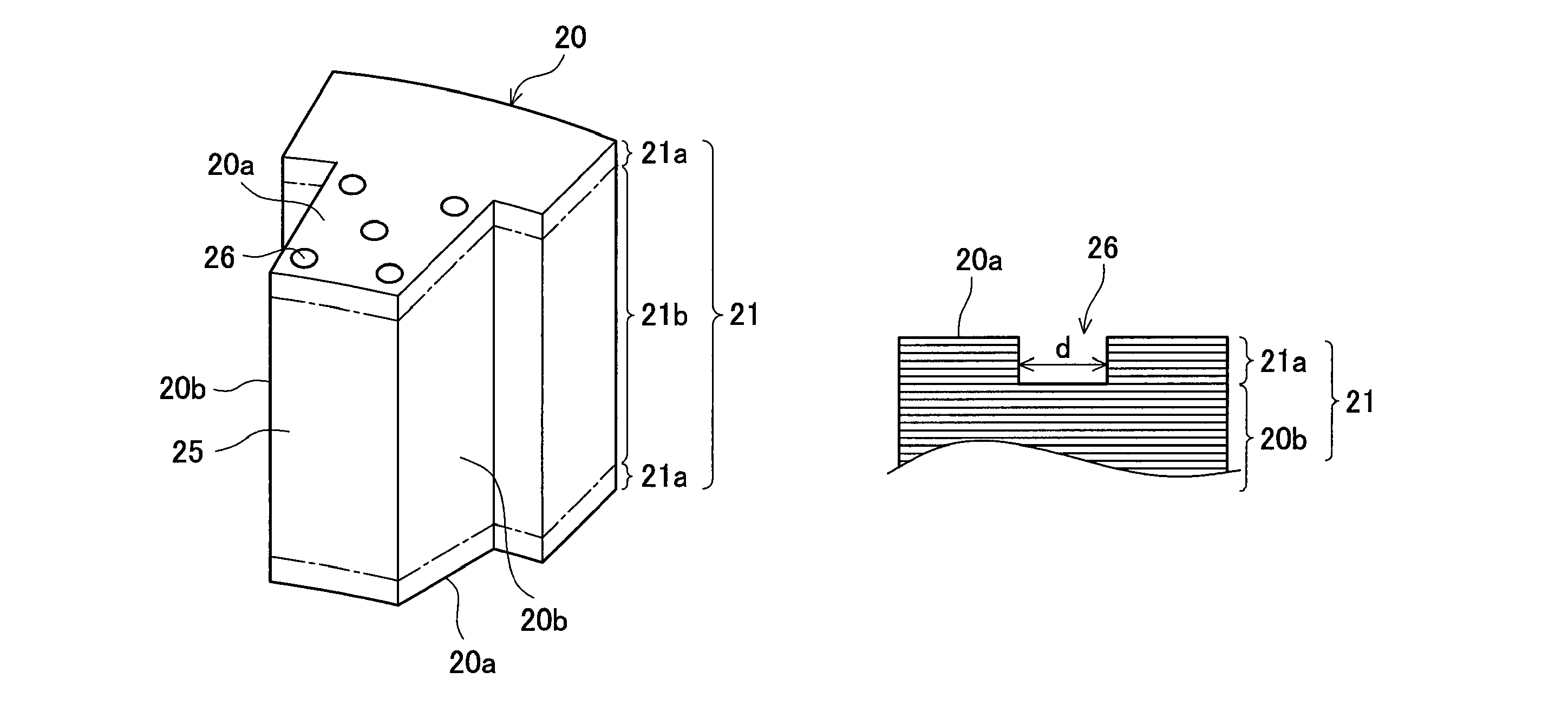
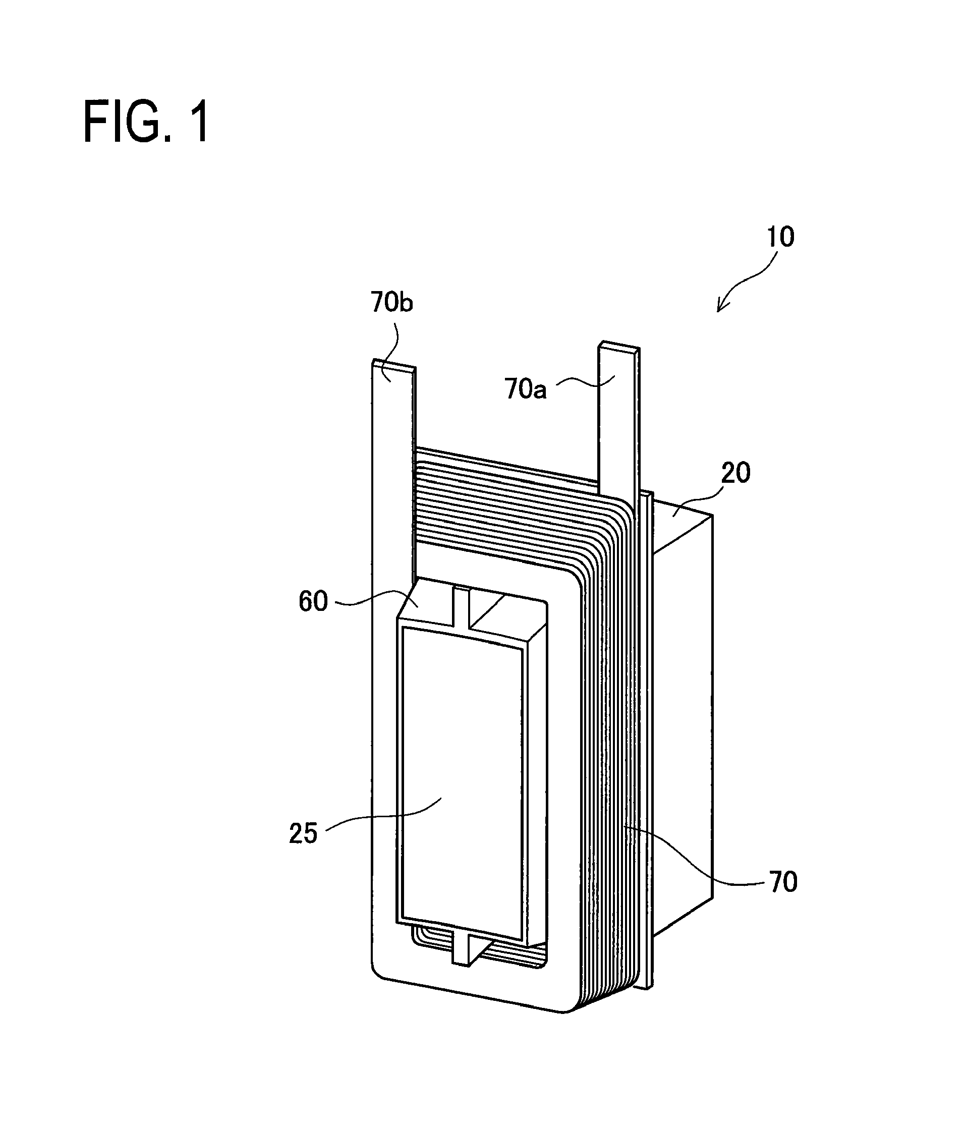
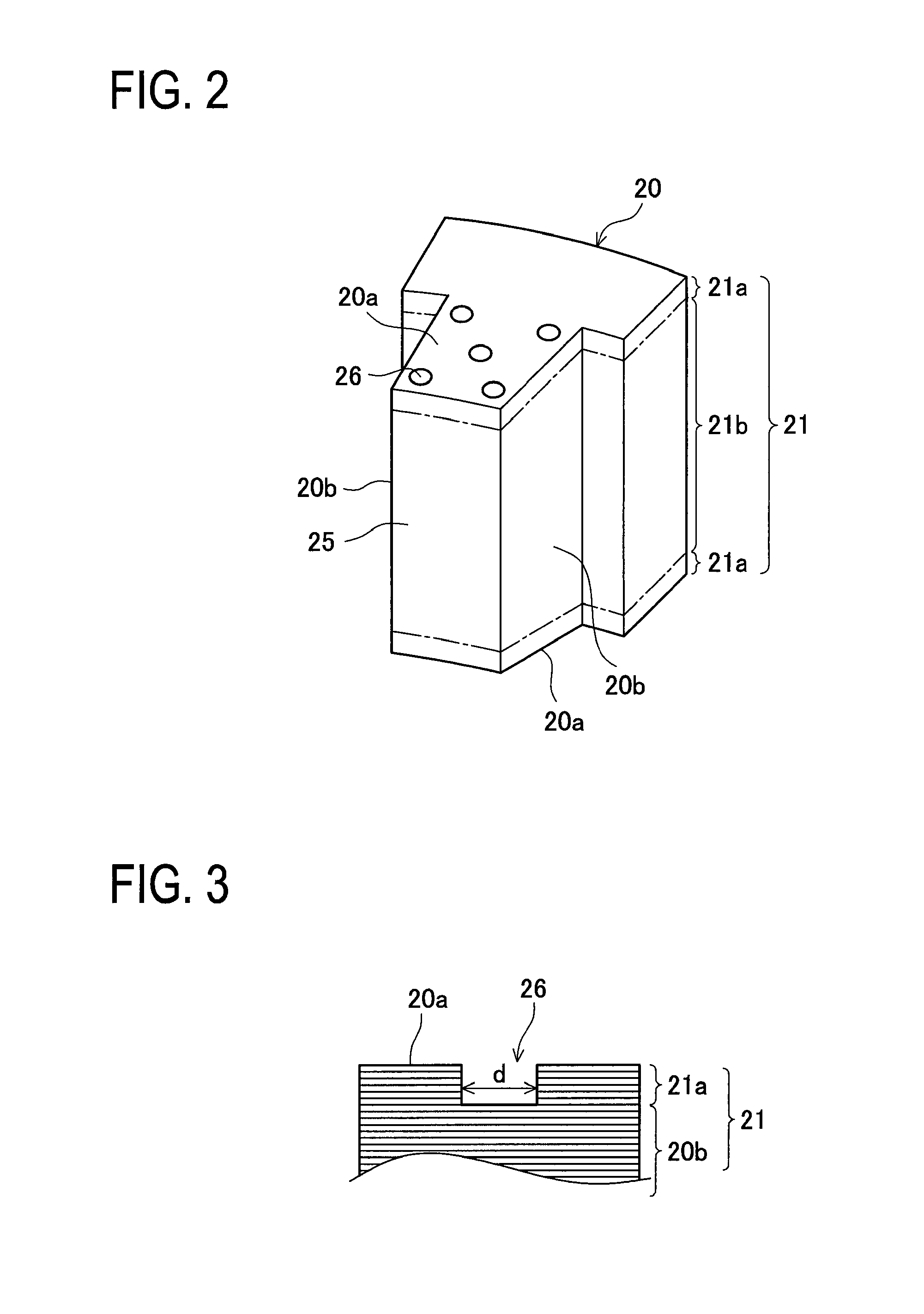
[0059]First, a first embodiment will be described. A split stator of the first embodiment will be briefly described with reference to FIGS. 1 to 6. FIG. 1 is a perspective view showing a schematic configuration of the split stator member according to the first embodiment. FIG. 2 is a perspective view showing a schematic configuration of a split stator core member. FIG. 3 is an enlarged sectional view of a part of the split stator core member in the vicinity of a bottomed hole. FIG. 4 is a perspective view showing a schematic configuration of an insulator molded to the split stator core member. FIG. 5 is a perspective view showing the split stator member covered with molding resin. FIG. 6 is a perspective view showing an annular stator configured by combining split stator members.
[0060]As shown in FIG. 1, a split stator member 10 includes a split stator core member 20, an insulator 60, and an edgewise coil 70. Then, the insulator 60 is resin molded (integrally molded) with the core m...
second embodiment
[0091]Next, a second embodiment will be described. In the second embodiment, recesses formed by a dimple process are formed in coil end faces as the slip prevention mechanism in place of the bottomed holes 26 in the first embodiment. Accordingly, a structure and a manufacturing method of the split stator member of the second embodiment are somewhat different from those of the first, embodiment. Thus, a point different from the first embodiment will be mainly described below. Note that the configurations common to those of the first embodiment are denoted by the same reference numerals in the drawings and the description of the configurations is appropriately omitted.
[0092]First, a stator member according to the second embodiment will be described with reference to FIGS. 14 and 15. FIG. 14 is a sectional view showing a part of the stator member according to the second embodiment and is an enlarged sectional view showing a recess formed in a coil end face and its surroundings. FIG. 15...
third embodiment
[0106]Next, a third embodiment will be described. In the third embodiment, adhesive layers are provided on coil end faces as the slip prevention mechanism in place of the bottomed holes 26 of the first embodiment. Accordingly, a structure and a manufacturing method of a split stator member are somewhat different from those of the first embodiment. Thus, a point different from the first embodiment will be mainly described below. Note that the configurations common to those of the first embodiment are denoted by the same reference numerals in the drawings and the description of the configurations is appropriately omitted.
[0107]First, a split stator member according to the third embodiment will be described with reference to FIG. 18. FIG. 18 is a sectional view showing the stator member according to the third embodiment and is an enlarged sectional view showing a coil end face and its surroundings.
[0108]As shown in FIG. 18, in the stator member in the third embodiment, an adhesive laye...
PUM
| Property | Measurement | Unit |
|---|---|---|
| Length | aaaaa | aaaaa |
| Diameter | aaaaa | aaaaa |
| Thermal conductivity | aaaaa | aaaaa |
Abstract
Description
Claims
Application Information