Prefabricated gravity type barrier wall

A gravity-type retaining wall technology, applied in construction, artificial islands, infrastructure engineering, etc., can solve problems such as long construction period and poor economic performance of retaining walls, reduce project cost, improve slope greening effect, build Convenience

Active Publication Date: 2017-10-24
易朋莹
View PDF7 Cites 3 Cited by
  • Summary
  • Abstract
  • Description
  • Claims
  • Application Information

AI Technical Summary

Problems solved by technology

[0003] The purpose of this invention is to solve the problems of poor economic performance and long construction period of traditional retaining walls, and provide a prefabricated gravity retaining wall

Method used


Image

  • Prefabricated gravity type barrier wall
  • Prefabricated gravity type barrier wall
  • Prefabricated gravity type barrier wall

Examples


Embodiment 1

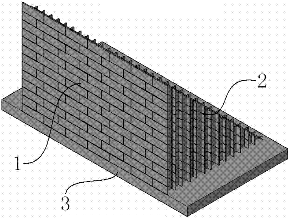
[0039] A prefabricated gravity retaining wall includes several wall prefabricated blocks 1, several wall prefabricated blocks 2, retaining wall foundation boards 3 and several steel bars.

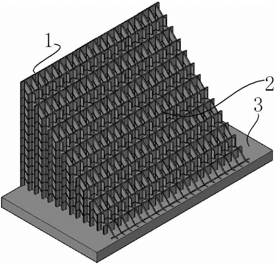
[0040] The wall prefabricated block 1 includes a vertical wall 101 and several concrete spacers 102 . The wall surface 101 and these concrete partition boards 102 are cast-in-place as an integral structure. The surfaces of the concrete partition boards 102 are vertical and interlaced with each other to form a plurality of hollow sash holes. The intersections of these concrete spacers 102 are provided with vertically through reserved holes 103 . One side of the prefabricated wall block 1 is a wall surface 101, and the peripheral grids on the other three circumferential sides are spliced ​​grids. When two adjacent wall prefabricated blocks 1 on the same horizontal plane are spliced ​​together, the spliced ​​sashes around them are combined to form a complete sash hole.

[0041] In this embo...

Embodiment 2

[0048] The main structure of this embodiment is substantially the same as that of Embodiment 1. Wherein the wall prefabricated block 1 and the wall prefabricated block 2 are both in the shape of steps. Their plan view and embodiment 1 Figure 8 , Figure 9 Not much difference. while the side view see Figure 11 and Figure 16 , between each step is a standard step surface perpendicular to each other, that is, one step corresponds to a vertical step surface.

[0049] That is to say, the prefabricated wall block 1 and the prefabricated wall block 2 of the present invention may be designed to be able to assemble each other. Their specific prototypes can be found in Figure 12 and Figure 17 , that is, the concrete sash at the same horizontal position, these concrete partitions 102 are arranged in a criss-cross pattern to form a rectangular sash, and when building masonry, as long as the joints are staggered from each other and the sash holes are connected to each other, it...

Embodiment 3

[0053] This embodiment provides a process installation method for a retaining wall, which specifically includes the following steps:

[0054] 1) According to the design of the retaining wall, the wall prefabricated block 1 and the wall prefabricated block 2 are made in the prefabrication yard.

[0055] 2) Prepare the mortar for the assembly of the above prefabricated blocks, and the connecting steel bars to be installed in the reserved holes.

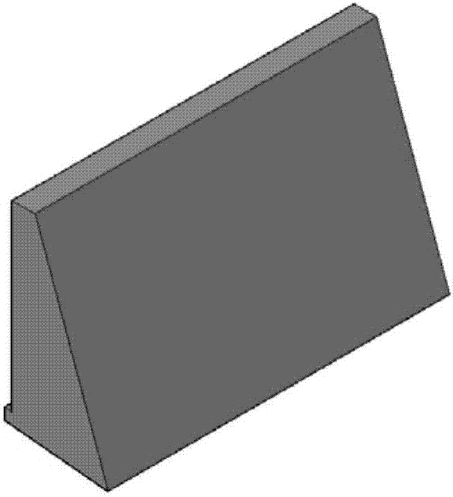
[0056] 3) Excavate the foundation groove on site, pour the retaining wall foundation plate 3, embed the connecting steel bars, and install the first layer of prefabricated wall blocks 1 and 2. 1 / 3-1 / 2 of the lower ends of these prefabricated blocks on the first floor are embedded in the base plate 3 of the retaining wall.

[0057] 4) After the strength of the base plate 3 of the retaining wall meets the construction requirements, backfill the soil in the grid hole, and compact the filled soil. Connect the reserved holes to connect the...


PUM


Abstract

The invention provides a prefabricated gravity type barrier wall. The prefabricated gravity type barrier wall comprises multiple wall face prefabricated blocks, multiple wall body prefabricated blocks, a barrier wall foundation plate and multiple reinforcing steel bars. The wall face prefabricated blocks and the wall body prefabricated blocks are designed into concrete grids which can be overlapped with one another for construction and mounted on the barrier wall foundation plate. Then, all the constructed prefabricated blocks are fixedly connected together through the reinforcing steel bars and mortar. Meanwhile, grid holes are filled with sandy soil so that the weight of the barrier wall can be increased. By means of the prefabricated gravity type barrier wall, the requirement for the bearing capacity of a foundation is low; concrete consumption is greatly saved; a scrapped soil body at site is fully converted into a wall body backfill construction material for the barrier wall; construction cost of a project is greatly saved; the construction period of the project is shortened; and the wall face ecological afforestation environment can be improved conveniently.

Description

technical field [0001] The invention relates to the technical field of construction engineering, in particular to a prefabricated gravity retaining wall. Background technique [0002] The gravity retaining wall is a retaining wall that relies on the wall's own weight to resist the lateral pressure of the soil. Gravity retaining walls can be built with block stones, flakes, and prefabricated concrete blocks as masonry, or with flake concrete and concrete for integral pouring, and are generally made into simple trapezoids, such as figure 1 shown. Because the gravity retaining wall maintains balance and stability by its own weight, its volume and weight are large, and it requires a high bearing capacity for the foundation; the gravity retaining wall is generally built with solid stone or concrete, and the amount of materials used is relatively large, which is relatively economical. Poor; and the gravity retaining wall is generally built or poured on site, the mortar or concre...

Claims


Application Information

Patent Timeline
Patent Type & Authority Applications(China)
IPC IPC(8): E02D29/02
CPCE02D29/0266
Inventor 易朋莹
Owner 易朋莹
Why Eureka
Try Eureka