Method for measuring spatial orientation of pipeline based on CMOS image sensor

A technology of image sensors and measuring pipelines, which is applied in the directions of measuring devices, instruments, surveying and navigation, etc., can solve the problems that the selection of recording points is greatly affected by the environment, the accuracy of collected data is low, and the measurement accuracy is reduced, so that the applicable method is flexible, The effect of high measurement accuracy and meeting the requirements of accuracy and breadth

Inactive Publication Date: 2017-10-24
NANJING UNIV OF SCI & TECH
View PDF4 Cites 7 Cited by
  • Summary
  • Abstract
  • Description
  • Claims
  • Application Information

AI Technical Summary

Problems solved by technology

[0003] Traditionally, two methods are used to measure the bending angle of pipelines: one is to use an angle measuring instrument. This method of data collection has the disadvantages of heavy post-processing workload, low accuracy of data collection, and the selection of recording points is greatly affected by the environment and is not continuous. The second is to use the probe head based on the electronic compass to walk in the tube, and transmit the measured data to the host computer through the cable to process and calculate the three-dimensional trajectory. However, the electronic compass will be interfered by the environmental magnetic field during the data transmission through the cable, resulting in loss of azimuth data. Accurate, the measurement accuracy is reduced, so it is only suitable for the environment without abnormal magnetic field interference

Method used


Image

  • Method for measuring spatial orientation of pipeline based on CMOS image sensor
  • Method for measuring spatial orientation of pipeline based on CMOS image sensor
  • Method for measuring spatial orientation of pipeline based on CMOS image sensor

Examples


Embodiment Construction

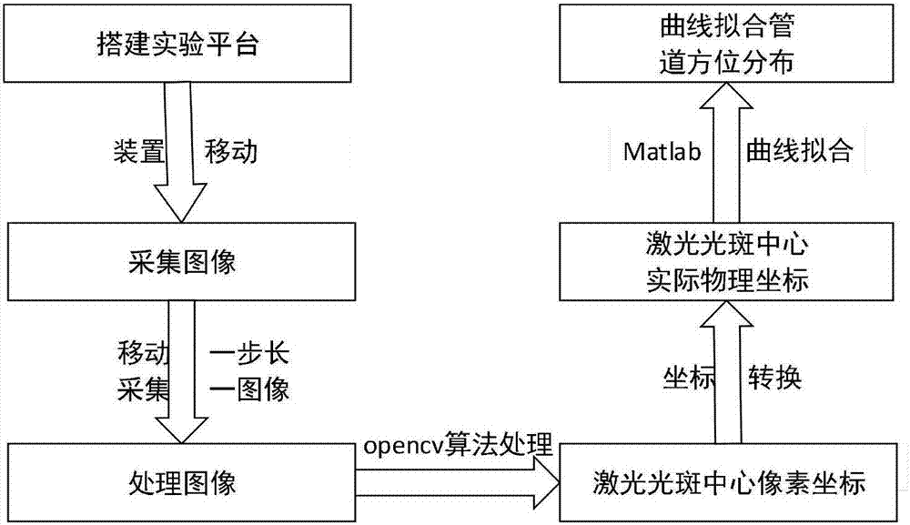
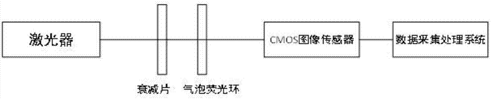
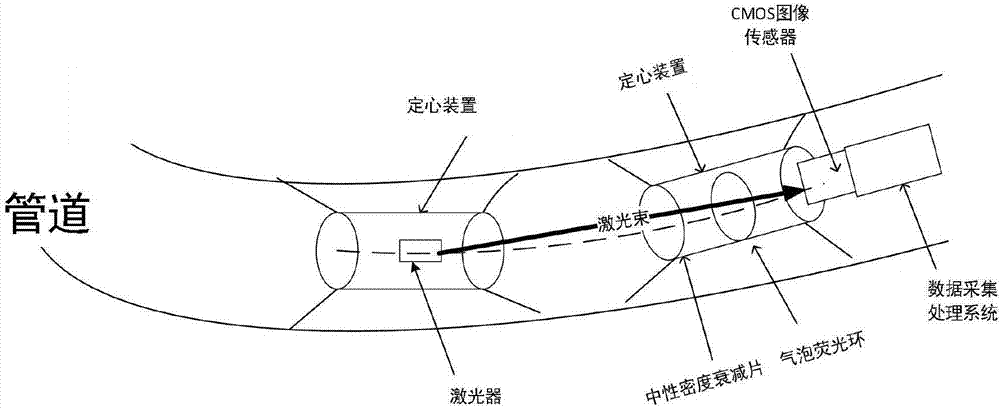
[0024] combine figure 1 , a method for measuring the spatial orientation of pipelines based on a CMOS image sensor. The laser beam emitted by a laser light source passes through a neutral density attenuator, passes through a bubble fluorescent ring, and is imaged on a CMOS image sensor. Through the image data acquisition and processing system, the acquired laser spot and bubble fluorescent ring images are analyzed and processed, including grayscale processing, adaptive median filtering, and the method of maximum class difference to obtain binary images, and then use the grayscale center of gravity method Calculate the pixel position of the laser spot on the photosensitive surface and the bubble position on the fluorescent ring. Use coordinate transformation to convert the pixel spot center to the actual physical spot center. When the centering device pauses every step forward, read the position of the laser spot at this position. By analogy, the positions of multiple measure...


PUM


Abstract

The invention provides a method for measuring the spatial orientation of a pipeline based on a CMOS image sensor. The method includes the following steps that: a laser light source and a CMOS image sensor are arranged at mechanical centering fixed ends at two ends of a universal joint, an attenuation sheet and a bubble fluorescent ring are arranged between the laser light source and the CMOS image sensor, the initial position of the laser light source is set, so that the initial position of the laser light source can be located at the center of the pipeline, and laser emitted by the laser light source is overlapped with the central axis of the pipeline; the laser light source moves, and the CMOS image sensor acquires one frame of image when the laser light source moves a certain distance each time from the initial position; laser spots and bubble fluorescent rings on the acquired images are processed, so that the pixel positions of the laser spots on a photosensitive surface and the directions of bubbles on the fluorescent rings are obtained, the center position of each laser spot and the position of each fluorescent ring bubbles are recorded; the center of each pixel light spot is converted into the actual physical position coordinates of a light spot center; and the orientation curve of the pipeline is fitted through using a least squares method-based curve fitting algorithm according to the actual physical position coordinates of the light spot center and the directions of the bubbles of the fluorescent rings.

Description

technical field [0001] The invention relates to a measurement and detection technology, in particular to a method for measuring the spatial orientation of a pipeline based on a CMOS image sensor. Background technique [0002] In engineering measurement, spatial angle measurement is very common, especially the spatial position measurement of pipelines. Generally, the pipeline trajectory is often quite different from the guiding design trajectory, especially after the completion of the measurement technology lags behind, resulting in a large error between the completion data of the underground pipeline project and the actual spatial position coordinates of the pipeline, which is not conducive to the construction of underground pipelines and social utilization. Therefore, it is very important to accurately grasp the underground space position of the completed pipeline. It is not only an index for evaluating the quality of the project, but also can provide a basis for the trajec...

Claims


Application Information

Patent Timeline
Patent Type & Authority Applications(China)
IPC IPC(8): G01B11/00G01C21/00
CPCG01B11/00G01C21/00
Inventor 汪贵华王柯杨栩
Owner NANJING UNIV OF SCI & TECH
Why Eureka
Try Eureka