
Wireless energy collecting device

A collection device and wireless energy technology, applied in the direction of circuit devices, battery circuit devices, current collectors, etc., can solve the problems of inability to reach the key device conversion device opening voltage, low sensitivity, difficult low power application, etc., to achieve maximum power transmission , low cost, simple way to achieve the effect

Inactive Publication Date: 2017-10-24
HUADA SEMICON CO LTD
View PDF1 Cites 2 Cited by
  • Summary
  • Abstract
  • Description
  • Claims
  • Application Information

AI Technical Summary

Problems solved by technology

However, the limitation of the current RF energy harvesting system is that its sensitivity is low, that is, the level converted by the antenna from the low-power RF signal is low, and it cannot reach the key components of the system, such as the conversion device of the RF-DC converter. turn-on voltage, making the conversion device inoperable, making such RF energy harvesting systems difficult to use for low-power applications

Method used


Image

  • Wireless energy collecting device
  • Wireless energy collecting device
  • Wireless energy collecting device

Examples


Embodiment Construction

[0047] It should be noted that the components in the drawings may be exaggeratedly shown for illustration purposes, and not necessarily in correct proportions. In the drawings, the same reference numerals are assigned to the same or the same components.

[0048] Unless otherwise specified, in this application, the quantifiers "one" and "one" do not exclude scenarios with multiple elements.

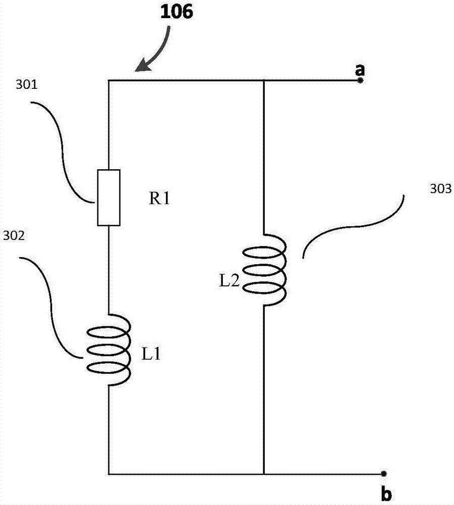
[0049] figure 1 A block diagram of the first embodiment of the wireless energy harvesting device 100 according to the present invention is shown.

[0050] Such as figure 1 As shown, the wireless energy harvesting device 100 includes an antenna 101 for receiving wireless signals and converting them into electric field signals. The wireless signal may be a radio frequency signal, but may also be a signal in other frequency bands, such as a microwave signal, which is understandable by those of ordinary skill in the art, and will not be listed here.

[0051] The wireless energy harvesting device 10...


PUM


Abstract

The invention relates to a wireless energy collecting device including an antenna, an antenna impedance conversion circuit, and a wireless DC converter, the antenna impedance conversion circuit is connected with the antenna to convert the impendence R antenna+jX antenna of the antenna to an R' antenna+jX' antenna, so that the R' antenna+jX' antenna of the antenna after the impedance conversion is conjugated with the impendence R antenna+jX antenna of the wireless DC converter; the wireless DC converter is connected with the antenna impedance conversion circuit to convert the output signal of the antenna impedance conversion circuit into a DC signal, wherein the impedance of the wireless DC converter is set the absolute value of an imaginary part X converter to be N times of the absolute value of a real part R converter, N>square root of 3. The device can achieve good voltage amplification and good impedance matching. The invention further relates to a passive voltage conversion matching circuit and a corresponding sensing device.

Description

Technical field [0001] The present invention generally relates to the field of wireless signal amplification, in particular to a wireless energy harvesting device, a passive voltage conversion matching circuit and a corresponding sensing device. Background technique [0002] The rise of the Internet of Things has brought tremendous convenience to people's lives, and the improvement of Internet of Things technology has become a goal pursued by the industry. One improvement goal is the power supply of its wireless sensor nodes. Wireless sensor nodes (which include one or more wireless sensors) are an important part of the Internet of Things, which are used for real-time data collection, processing, and transmission of networked devices. Due to the huge number of wireless sensor nodes, their power supply has become a prominent problem. For example, suppose an IoT sensor network has 10,000 wireless sensor nodes, and the battery of each sensor node can last for 4 years, then about 6...

Claims


Application Information

Patent Timeline
Patent Type & Authority Applications(China)
IPC IPC(8): H02J50/20H02J7/02
CPCH02J50/20H02J7/025
Inventor 王伟印王永流李荣信
Owner HUADA SEMICON CO LTD
Learn More