Al technical title is built by PatSnap Al team. It summarizes the technical point description of the patent document.
A technology of power modulation and voltage regulator, which is applied in the direction of output power conversion device, conversion of AC power input to DC power output, electrical components, etc., and can solve problems such as unable to adjust power and voltage, and difficult to apply generator excitation system
Active Publication Date: 2017-10-24
重庆赛能软件技术有限公司
View PDF4 Cites 0 Cited by
Summary
Abstract
Description
Claims
Application Information
AI Technical Summary
This helps you quickly interpret patents by identifying the three key elements:
Problems solved by technology
Method used
Benefits of technology
Problems solved by technology
[0004] The technical problem to be solved by the present invention is that the existing thyristor power and voltage regulator cannot regulate power and voltage for any two phases in the three-phase circuit, so it is difficult to apply it to the generator excitation system, and the purpose is to provide controllable Silicon Power Modulators, Addressing the Issues Above
Method used
Image
Click on the blue label to locate the original text in one second.
Reading with bidirectional positioning of images and text.
Examples
Embodiment
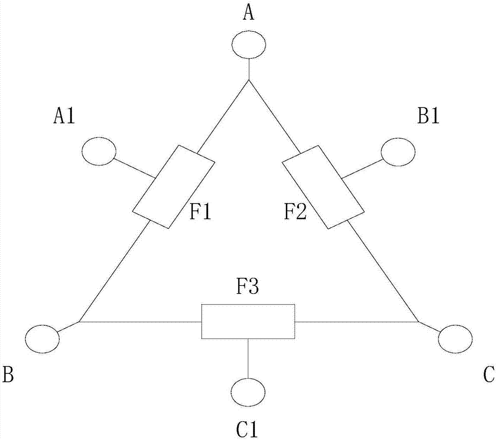
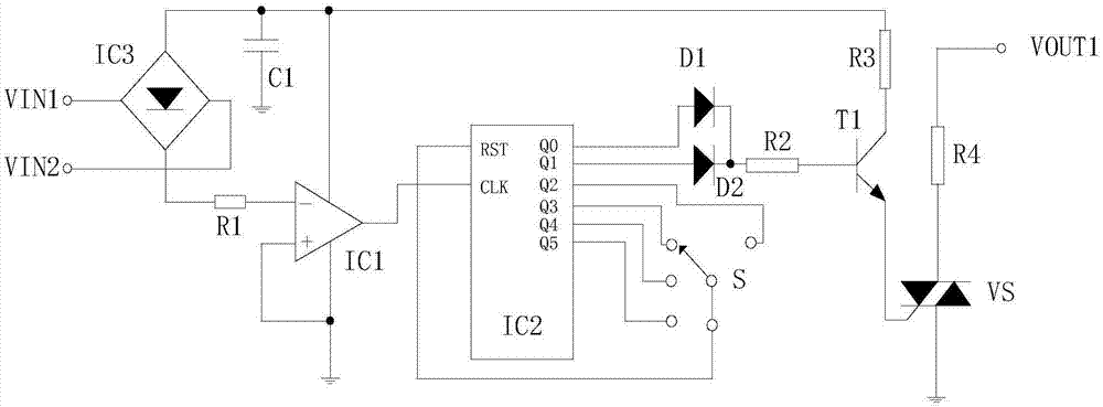
[0019] Such as figure 1 As shown, the thyristor power modulator of the present invention includes three-phase electrical interfaces A, B and C, and also includes power and voltage regulation interfaces A1, B1 and C1; said A and B are connected to the input of the power and voltage regulator F1 terminal, and A1 is connected to the output terminal of the power regulator F1; the A and C are connected to the input terminal of the power regulator F2, and B1 is connected to the output terminal of the power regulator F2; the B and C are connected The input terminal of the power regulator F3, and C1 is connected to the output terminal of the power regulator F3; the structures of the F1, F2 and F3 are the same, and F1 includes a first resistor R1, a second resistor R2, a third resistor R3, fourth resistor R4, first diode D1, second diode D2, capacitor C1, operational amplifier IC1, pulse distributor IC2, rectifier IC3, bidirectional thyristor VS, first input terminal VIN1, second input...
PUM
Abstract
The invention discloses a silicon controlled rectifier power modulator. The silicon controlled rectifier power modulator comprises three-phase electrical interfaces A, B and C, and power and voltage regulating interfaces A1, B1 and C1, wherein the A and the B are connected with an input end of a power and voltage regulator F1, and the A1 is connected with an output end of the power and voltage regulator F1; the A and the C are connected with an input end of a power and voltage regulator F2, and the B1 is connected with an output end of the power and voltage regulator F2; the B and the C are connected with an input end of a power and voltage regulator F3, and the C1 is connected with an output end of the power and voltage regulator F3; the F1, the F2 and the F3 are of the same structure; two input ends of an IC3 are connected with a VIN1 and a VIN2, an output end of the IC3 is connected with a positive power supply interface of an IC1, another output end of the IC3 is connected with one end of an R1, and the other end of the R1 is connected with an inverting input end of the IC1. According to the silicon controlled rectifier power modulator, the F1, the F2 and the F3 form the new three-phase output ends A1, B1 and C1, thus voltage and power between any two of the A1, the B1 and the C1 can be adjusted easily, and the silicon controlled rectifier power modulator can be applied to generator excitation system.
Description
technical field [0001] The invention relates to the field of power generation control, in particular to a thyristor power modulator. Background technique [0002] Thyristor, the abbreviation of silicon controlled rectifier element, is a high-power semiconductor device with a four-layer structure of three PN junctions, also known as a thyristor. With the characteristics of small size, relatively simple structure, and strong functions, it is one of the more commonly used semiconductor devices. The device is widely used in various electronic equipment and electronic products, and is mostly used for controllable rectification, inverter, frequency conversion, voltage regulation, non-contact switch, etc. Dimming lamps, speed-adjusting fans, air conditioners, televisions, refrigerators, washing machines, cameras, combined audio systems, sound and light circuits, timing controllers, toy devices, radio remote controls, cameras and industrial controls in household appliances are wide...
Claims
Application Information
Patent Timeline
Application Date:The date an application was filed.
Publication Date:The date a patent or application was officially published.
First Publication Date:The earliest publication date of a patent with the same application number.
Issue Date:Publication date of the patent grant document.
PCT Entry Date:The Entry date of PCT National Phase.
Estimated Expiry Date:The statutory expiry date of a patent right according to the Patent Law, and it is the longest term of protection that the patent right can achieve without the termination of the patent right due to other reasons(Term extension factor has been taken into account ).
Invalid Date:Actual expiry date is based on effective date or publication date of legal transaction data of invalid patent.