Rapid Pneumatic Bulging Method for Hot Metal Sheet

A technology of metal sheet and metal slab, which is applied in the field of sheet metal parts forming, can solve the problems of inability to realize the precision and rapid prototyping of thin-walled parts of complex metal sheet metal parts, and the inability to guarantee the deformation of the blank, so as to achieve gas pressure maintenance and pressure difference distribution controllable effect

Active Publication Date: 2019-11-15
HARBIN INST OF TECH
View PDF6 Cites 0 Cited by
  • Summary
  • Abstract
  • Description
  • Claims
  • Application Information

AI Technical Summary

Problems solved by technology

[0005] The present invention aims to solve the problem that the existing hot metal sheet forming technology cannot ensure that the blank is deformed under reasonable temperature and pressure conditions, so that the precise and rapid forming of complex metal sheet metal parts, especially thin-walled parts, cannot be realized. Propose a method for rapid air bulging of hot metal sheet

Method used


Image

  • Rapid Pneumatic Bulging Method for Hot Metal Sheet
  • Rapid Pneumatic Bulging Method for Hot Metal Sheet
  • Rapid Pneumatic Bulging Method for Hot Metal Sheet

Examples


specific Embodiment approach 1

[0049] Specific implementation mode one: see Figure 5-Figure 8 and Figure 10 Illustrates that the rapid gas bulging method of the hot metal sheet material is realized according to the following steps:

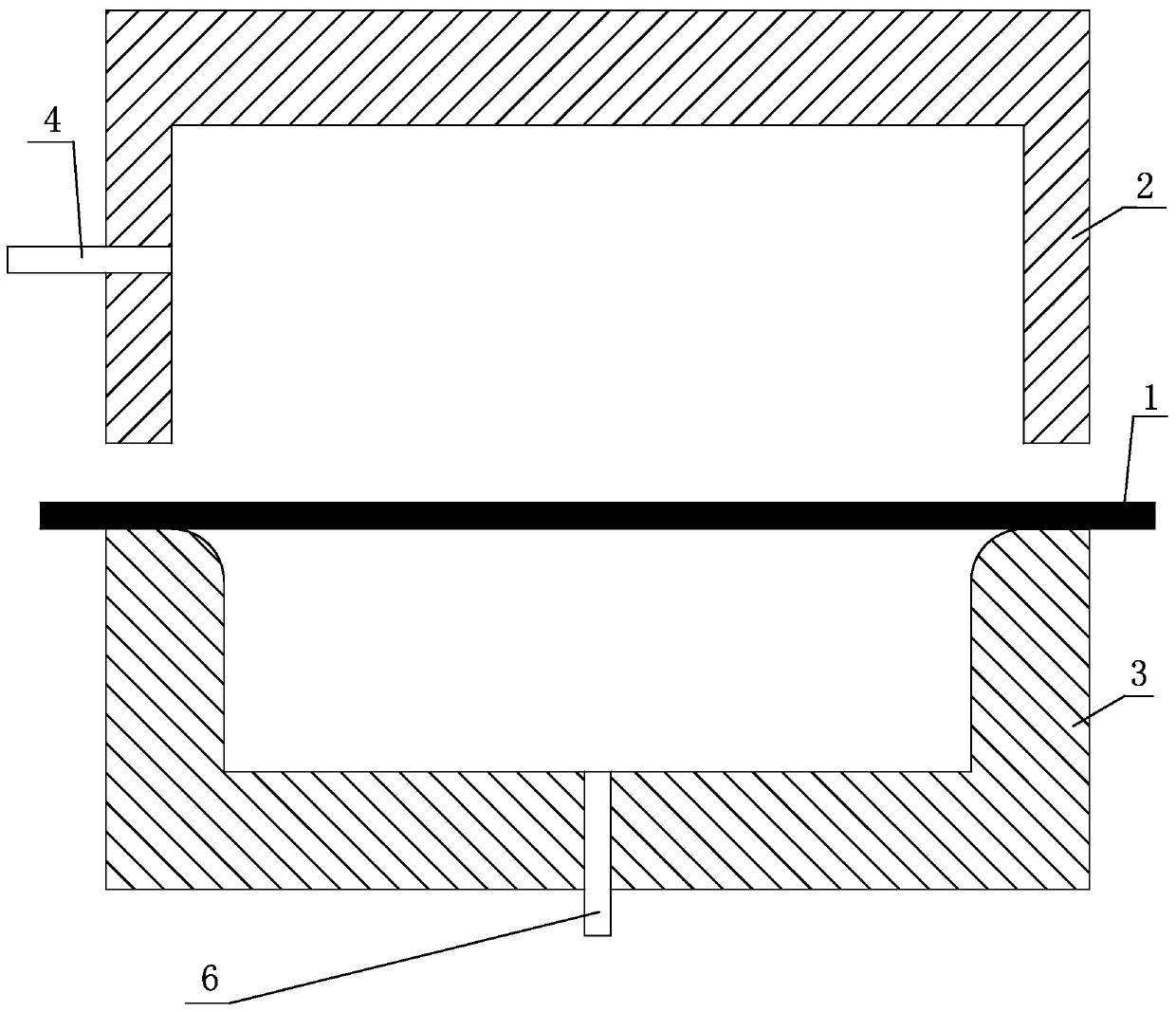
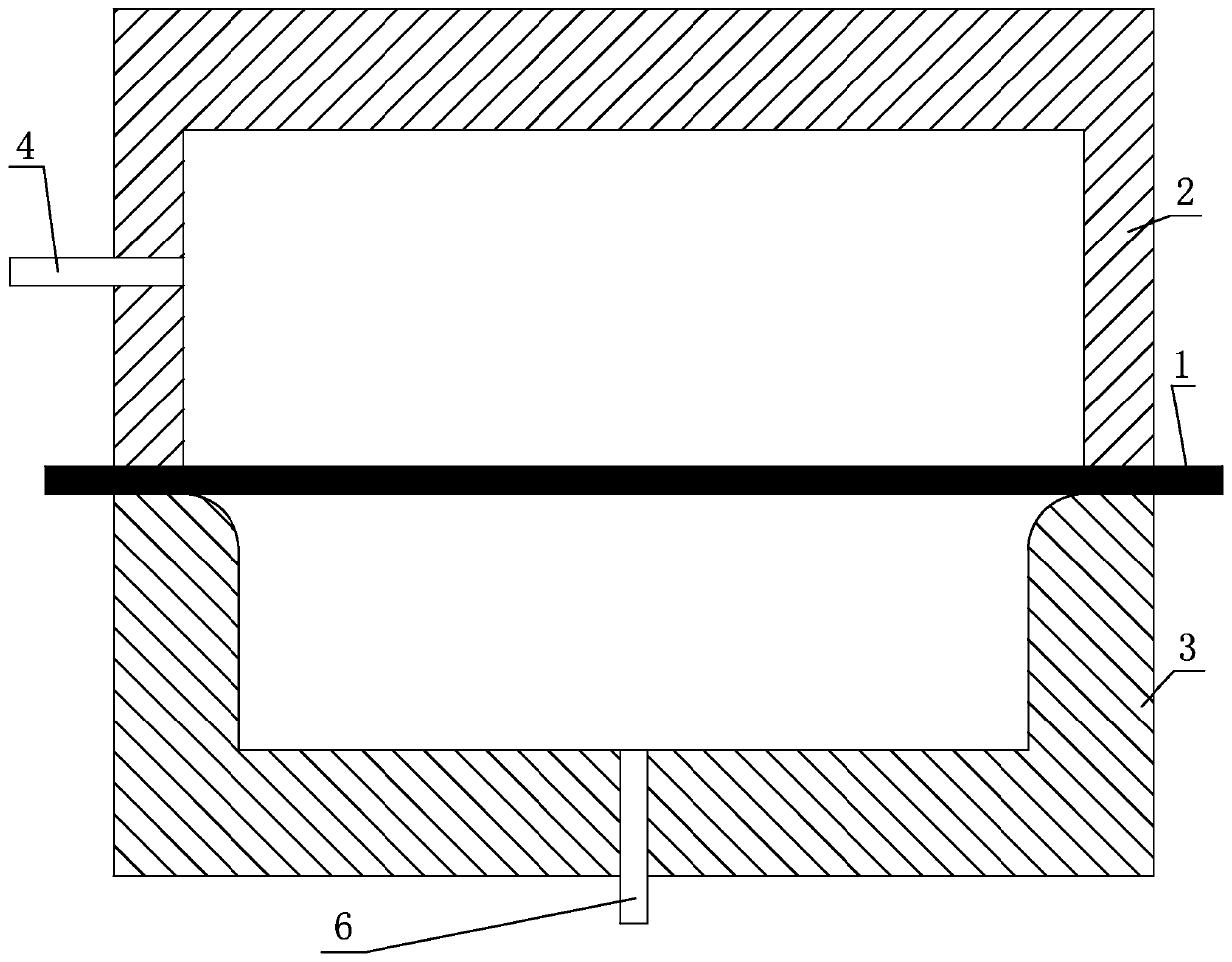
[0050] Step 1, placing the metal slab 1 to be formed on the forming mold 3, closing the sealing mold 2 to form a closed cavity on the upper and lower surfaces of the metal slab 1;

[0051] Step 2: filling the upper and lower airtight cavities formed by the upper air hole 4 and the lower air hole 5 into the upper and lower airtight cavities formed by the metal slab 1 and the sealing mold 2, and the metal slab 1 and the forming mold 3 respectively;

[0052] Step 3, heating the metal slab 1 to a preset forming temperature condition;

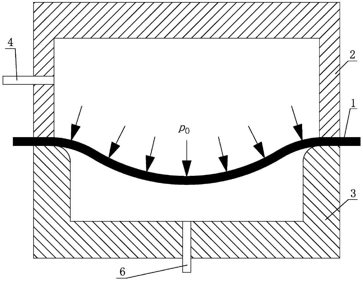
[0053] Step 4, quickly release the high-pressure gas in the airtight cavity formed by the metal slab 1 and the forming die 3 by the vent hole 6, so that the high pressure gas in the airtight cavity formed by the metal slab 1 and the sealing mold ...

specific Embodiment approach 2

[0060] Specific implementation mode two: see Figure 5-Figure 8 , Figure 10 , Figure 12-Figure 14 Note that the difference between this embodiment and the specific embodiment 1 is that in step 3, the heating method of the metal slab is limited, such as external preheating of the mold, steel plate contact heating, mold radiation heating, etc., and the metal slab is isothermal and non-isothermal, specifically : In step one, the sealing mold 2 and forming mold 3 that are adopted are all in a hot state, and its temperature is T 2 . The predetermined forming temperature of metal slab 1 is T 0 . The sheet metal blank 1 is preheated to a temperature T before being placed in the sealing mold 3 and the forming mold 2 1 . When T 1 less than T 0 , then T 2 > T 0 , to use the mold to reheat the metal slab 1 to reach the predetermined forming temperature T 0 . When the original metal slab 1 is larger in size and far away from the mold cavity, a hot steel plate 7 can be placed...

specific Embodiment approach 3

[0062] Specific implementation mode three: see Figure 5-Figure 8 , Figure 10 and Figure 15-Figure 17 Note that the difference between this embodiment and the specific embodiment 1 or 2 is that the arrangement of the vent holes is limited, and different arrangements are adopted for different parts, specifically: in step 4, there are A plurality of vent holes 6 are unevenly distributed, vent hole one 6-1 is located on the left side of the cavity, vent hole two 6-2 and vent hole three 6-3 are located on the right side of the cavity.

[0063] In this embodiment, when the airtight cavity of the forming die 3 is a complex asymmetric structure, by reasonably setting the number and positions of the vent holes 6, the airtight cavity formed by the metal slab 1 and the forming die 3 can be The high-pressure gas is quickly released to normal pressure at almost the same speed, so that an approximately uniform pressure difference can be quickly formed on the upper surface and the lower...


PUM


Abstract

Provided is a method for quick forming of a hot metal sheet. The method relates to a technology for forming a metal sheet part, and solves the problem that the existing hot metal sheet forming technology cannot ensure that a blank is deformed under reasonable temperature and pressure conditions, thereby failing to realize precise and quick forming of a complex metal sheet part, especially a thin-walled part. The method mainly includes the following steps: step one, placing a metal sheet blank to be formed on a forming mold; step two, introducing high-pressure gases with equal pressures simultaneously into upper and lower enclosed cavities respectively formed by the metal sheet blank and the sealing mold, and the metal sheet blank and the forming mold; step three, heating the metal sheet blank to a preset forming temperature condition; step four, quickly releasing the high-pressure gas from the cavity formed by the metal sheet blank and the forming mold, such that the metal sheet blank bulges; and step five, discharging the gas from the cavity formed by the metal sheet blank and the sealing mold, and opening the mold to obtain a formed metal sheet part. The present invention is used for manufacturing a metal sheet part.

Description

technical field [0001] The invention relates to the forming technology of sheet metal parts, in particular to a method capable of realizing rapid gas bulging of sheet metal in a hot state. Background technique [0002] The manufacture of metal sheet metal components mainly relies on the plastic deformation ability of metal materials, and the blank is plastically deformed by externally applied loads. For different metal materials, different forming processes and forming conditions are required. [0003] Due to the low density and high specific strength of materials such as aluminum alloys, magnesium alloys and titanium alloys, parts of the same quality can provide higher load carrying capacity, so such materials are called lightweight materials. A common disadvantage of such materials is poor plasticity at room temperature, making it difficult to manufacture complex parts at room temperature. At present, the hot forming method is mainly used to form such materials, that is,...

Claims


Application Information

Patent Timeline
Patent Type & Authority Patents(China)
IPC IPC(8): B21D26/021
CPCB21D26/021B21D26/027B21D26/055B21D37/16B21D26/025B21D26/029B21D53/045
Inventor 苑世剑何祝斌凡晓波丁名区韩国丰
Owner HARBIN INST OF TECH
Why Eureka
Try Eureka