Radiating water tank and plastic shield assembly

A technology of cooling water tank and shield, which is applied in the layout of power unit cooling combination, power unit, transportation and packaging, etc., can solve the problems of poor water circulation inside the water tank, inconsistency of installation lugs, and weak impact resistance. , to achieve the effect of more beautiful appearance, good water circulation, and improved impact resistance.

Active Publication Date: 2015-03-04
重庆和金汽车配件有限公司
View PDF4 Cites 0 Cited by
  • Summary
  • Abstract
  • Description
  • Claims
  • Application Information

AI Technical Summary

Problems solved by technology

The existing circulating heat dissipation water tank has poor structural strength, is prone to bulging and deformation, has weak impact resistance, and the water circulation inside the water tank is not good
At the same time, the installation lugs of the circulating cooling water tank are not concentrated, on the one hand, it is inconvenient to install and the assembly efficiency is low; on the other hand, the lugs are prone to breakage, which will cause the water tank to loosen or fall off

Method used


Image

  • Radiating water tank and plastic shield assembly
  • Radiating water tank and plastic shield assembly
  • Radiating water tank and plastic shield assembly

Examples


Embodiment Construction

[0022] Below in conjunction with accompanying drawing and embodiment the present invention will be further described:

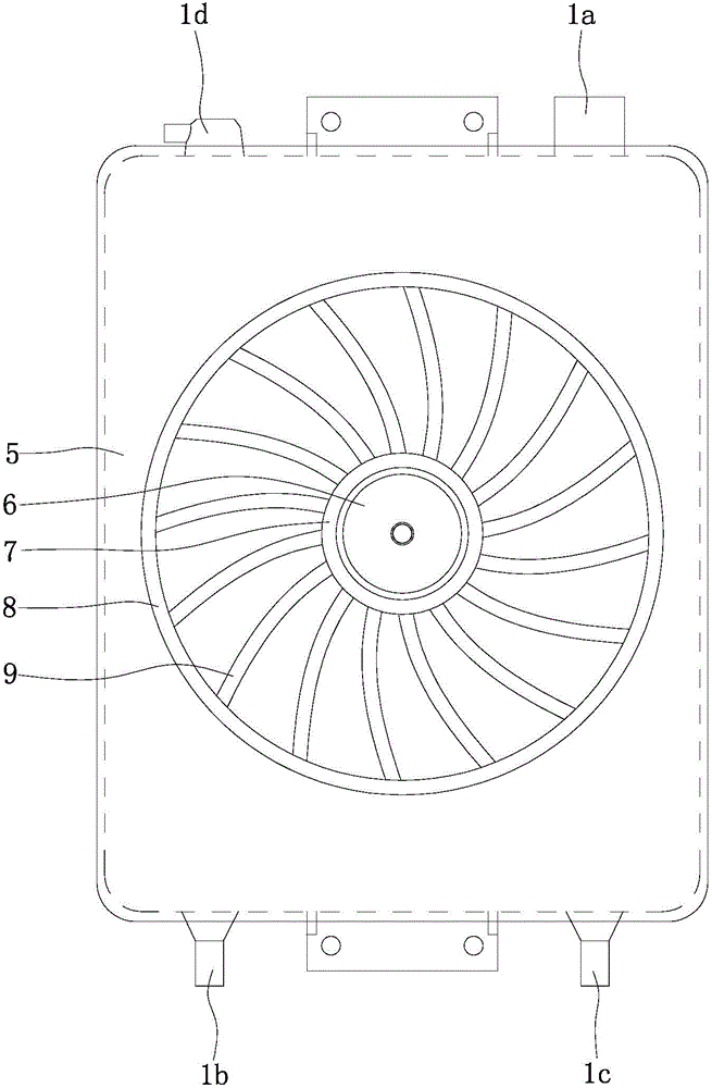
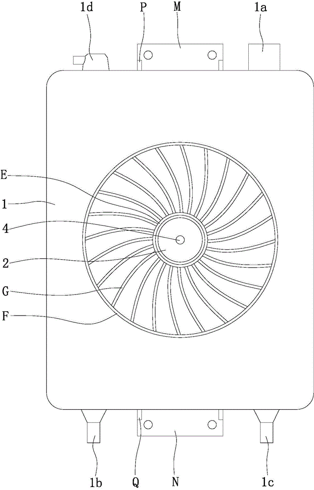
[0023] Such as figure 2 , image 3 As shown, the box body 1 is rectangular and molded by hollow blow molding. The pressure-reducing vent nozzle 1d is set on the left end of the top of the box body 1, and the water inlet 1a is set on the right end of the top of the box body 1; the water inlet 1b is set on the left end of the bottom of the box body 1, and the water outlet 1c is set on the right end of the bottom of the box body 1 . The pressure-reducing air nozzle 1d, the water inlet 1a, the water inlet 1b, the water outlet 1c and the box body 1 are integrated.

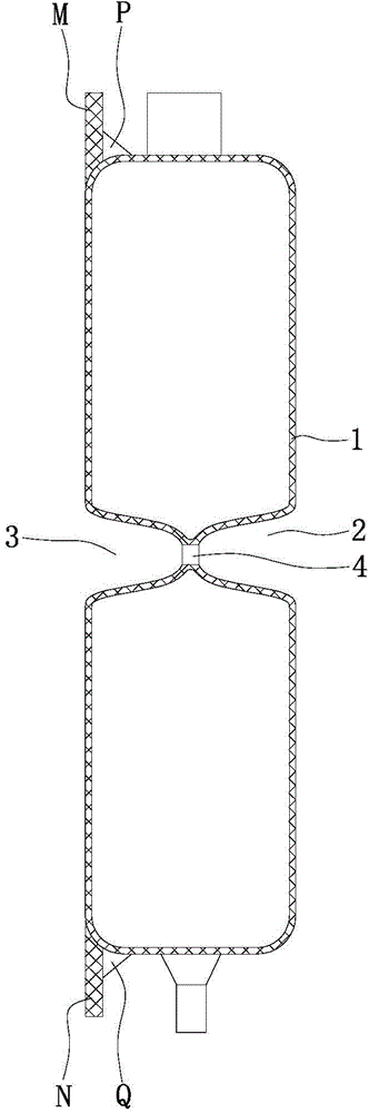
[0024] Such as figure 2 , image 3 As shown, the middle part of the front box wall of the box body 1 is recessed backwards to form a first sinker 2, the first sinker 2 is conical, and the first sinker 2 gradually becomes smaller from the notch to the bottom of the tank. The position of the rear...


PUM


Abstract

The invention discloses a radiating water tank and plastic shield assembly. An upper positioning plate (M) extending up is integrated to the middle of the top end of the rear wall of a tank body (1); a lower positioning plate (N) extending down is integrated to the bottom end of the rear wall of the tank body (1); the front of the tank body (1) is covered by a shield (5); the middle of the shield (5) is provided with a conical tube (6); an inner protrusion (7) which is circular is provided around an opening of the conical tube (6); an outer protrusion (8) concentric with the inner protrusion (7) is provided outside the inner protrusion (7). The radiating water tank and plastic shield assembly has the advantages that the tank body is high in structural strength, high in impact resistance and free of bulging; mounting points of the tank body are in plate structures, firmness is good, and breakage never occurs; the shield is provided outside the tank body, attractiveness is achieved, protection is also achieved, and the shield is convenient to demount and mount and firm and reliable to connect; the shield is provided with a vent structure, and good radiating performance of the tank body is ensured.

Description

technical field [0001] The invention relates to a water tank, in particular to a connection assembly between a circulating cooling water tank and a shield on a three-wheeled motorcycle. Background technique [0002] The circulating cooling water tank is an important part on the three-wheeled motorcycle, which is used to provide circulating cooling water to the radiator. The existing circulating heat dissipation water tank has poor structural strength, is prone to bulging and deformation, has weak impact resistance, and the water circulation inside the water tank is not good. At the same time, the installation lugs of the circulating cooling water tank are not concentrated, on the one hand, it is inconvenient to install and the assembly efficiency is low; on the other hand, the lugs are prone to breakage, which will cause the water tank to loosen or fall off. Contents of the invention [0003] The technical problem to be solved by the present invention is to provide a comb...

Claims


Application Information

Patent Timeline
Patent Type & Authority Applications(China)
IPC IPC(8): B60K11/02
Inventor 叶和全
Owner 重庆和金汽车配件有限公司
Why Eureka
Try Eureka