Eureka AIR delivers breakthrough ideas for toughest innovation challenges, trusted by R&D personnel around the world.

Control system and control method capable of automatically judging and setting laser frequency and power

An automatic judgment and control system technology, applied in the field of optoelectronics, can solve problems such as equipment not working properly, affecting the output frequency of the laser, adjusting the laser frequency to the target value, etc.

Active Publication Date: 2017-10-27
PEKING UNIV
View PDF4 Cites 12 Cited by
  • Summary
  • Abstract
  • Description
  • Claims
  • Application Information

AI Technical Summary

Problems solved by technology

In addition, the length of the resonant cavity is very susceptible to interference from various environmental factors (such as environmental temperature changes, humidity changes, mechanical vibrations, etc.), which will cause the resonant frequency of the cavity to drift, thereby affecting the output frequency of the laser
[0005] Aging will cause the laser to reach the output frequency required by the system under the initial setting temperature condition, the power of the output light will decrease, and the intensity of the generated measurement signal will decrease, so that the index of the whole device will decrease or even fail; When there are large fluctuations, the laser cannot adjust the laser frequency to the target value by adjusting the injection current at the original set temperature, or the laser temperature may not be locked to the original set value, so that the equipment cannot work normally

Method used


Image

  • Control system and control method capable of automatically judging and setting laser frequency and power

Examples


Embodiment Construction

[0045] The present invention will be further elaborated below through specific embodiments in conjunction with the accompanying drawings.

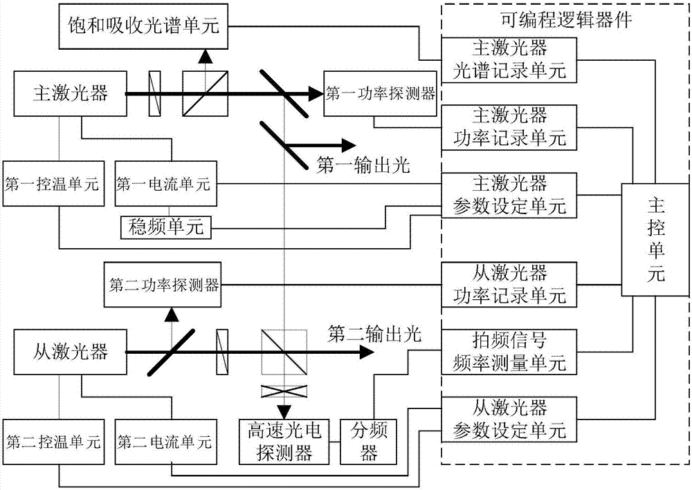
[0046] like figure 1As shown, the control system for automatically judging and setting the laser frequency and power in this embodiment includes: a master laser, a slave laser, a first temperature control unit, a second temperature control unit, a first current unit, a second current unit, and a second current unit. A power detector, a second power detector, a saturated absorption spectrum unit, a frequency stabilization unit, a high-speed photodetector, a frequency divider, a first high-reflection beam splitter, a second high-reflection beam splitter, a high-transmission beam splitter, a first A half-wave plate, a second half-wave plate, a quarter-wave plate, a first polarizing beam splitting prism, a second polarizing beam splitting prism, and a programmable logic device CPLD; wherein, the programmable logic device CPLD The master laser...


PUM


Abstract

The invention discloses a control system and a control method capable of automatically judging and setting a laser frequency and power. According to the invention, a double-laser structure is adopted; a main control unit can automatically search and automatically judge an output frequency of a main laser according to a spectrum signal, and automatically locks the frequency onto an atom or molecule spectral line after automatically optimizing an output power of the main laser to a target power; after outputs of a slave laser and the main laser are subjected to beam combination, a beat frequency signal is generated, and the main control unit can automatically judge a size relationship of the output frequencies of the main laser and the slave laser so as to accurately and automatically judge the output frequency of the slave laser, after the output power of the slave laser is automatically optimized to the target power, a frequency locking error signal is generated by utilizing the main control unit, and in a range of 80GHz, locking on the frequency of the slave laser is implemented; and the method disclosed by the invention can be widely applied to the technical fields of fundamental researches and precision measurement of laser cooling, atomic frequency standards, an atom interferometer, a laser wavelength meter and the like.

Description

technical field [0001] The invention belongs to the technical field of optoelectronics, and in particular relates to a control system and a control method for automatically judging and setting laser frequency and power. Background technique [0002] In precision measurement equipment related to frequency-stabilized lasers and devices using high-frequency precision lasers, it is usually necessary to tune and lock the output frequency of the laser within a wide range. Laser aging, parameter drift or large fluctuations in the working environment will cause the laser frequency to drift out of the system locking range, resulting in equipment failure or index decline. If the laser has the function of automatically judging and automatically setting the frequency, the index of the equipment has been averaged. The time between failures will increase significantly. [0003] Generally, in a frequency-stabilized laser or a device or device using a high-frequency precision laser, it is ...

Claims


Application Information

Patent Timeline
IPC IPC(8): H01S3/13
CPCH01S3/13H01S3/1305
Inventor 熊炜张胤王平俊陈徐宗
Owner PEKING UNIV
Why Eureka
Eureka Blog
Learn More