Double-side staggered-tooth low thrust fluctuation permanent magnetic synchronous linear motor

A permanent magnet synchronous linear, low thrust technology, applied in electrical components, electromechanical devices, propulsion systems, etc., can solve problems such as thrust fluctuations of dual-primary permanent magnet synchronous linear motors, and achieve the effect of improving performance and suppressing thrust fluctuations

Inactive Publication Date: 2017-10-27
NANJING UNIV OF AERONAUTICS & ASTRONAUTICS
View PDF3 Cites 6 Cited by
  • Summary
  • Abstract
  • Description
  • Claims
  • Application Information

AI Technical Summary

Problems solved by technology

[0003] In order to solve the problem of large thrust fluctuations of the existing dual-primary permanent magnet synchronous linear motors, the present invention proposes a permanent magnet synchronous linear motor with bilateral staggered teeth and low thrust fluctuations

Method used


Image

  • Double-side staggered-tooth low thrust fluctuation permanent magnetic synchronous linear motor
  • Double-side staggered-tooth low thrust fluctuation permanent magnetic synchronous linear motor
  • Double-side staggered-tooth low thrust fluctuation permanent magnetic synchronous linear motor

Examples


Embodiment approach 1

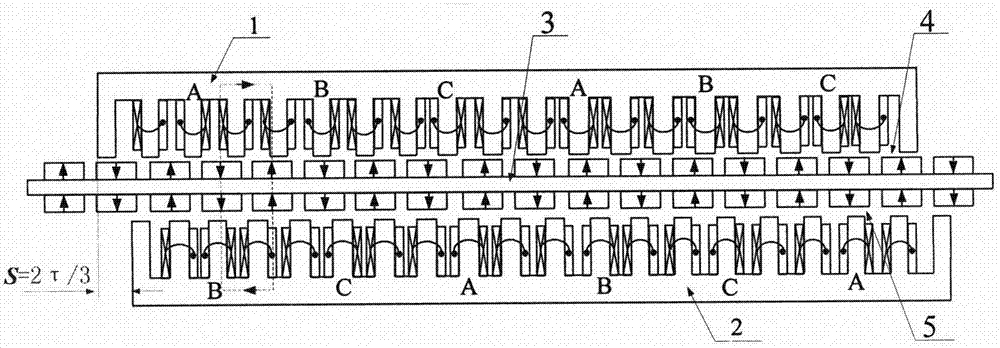
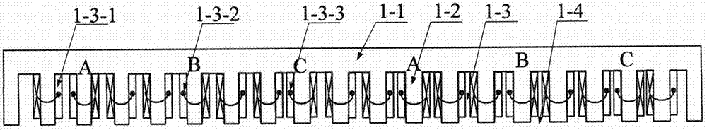
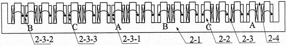
[0022] Such as figure 1 , 2 As shown in, 3, 4, and 5, this embodiment is a double-sided staggered 2τ / 3 low-thrust-pulsation permanent magnet synchronous linear motor, and its pole-slot coordination is a 16-pole 18-slot structure. Double-sided staggered teeth 2τ / 3 low thrust fluctuation permanent magnet synchronous linear motor, which includes a primary component 1, a primary component 2 and a secondary component 3. The primary component 1 consists of a core yoke 1-1, core teeth 1-2 and armature winding 1-3. Primary component two 2 is composed of core yoke 2-1, core teeth 2-2 and armature winding 2-3. The secondary assembly 3 is composed of a permanent magnet 3-1 and a yoke plate 3-2. Each pair of poles includes four permanent magnets. The permanent magnets 3-1-1 and 3-1-3 are located on both sides of the yoke plate 3-2. The magnetizing direction of the permanent magnet 3-1-2 is the same as that of the permanent magnet 3-1-4. The adjacent permanent magnets 3-1-1 and 3-1-2 loca...

Embodiment approach 2

[0028] The difference between this embodiment and the first embodiment is: Image 6 with Figure 7 As shown, the displacement of the primary component 1 and the primary component 2 in the lateral direction is S=τ / 3 (τ is the pole pitch of the motor), that is, the electric angle is 60°.

[0029] On the primary component 1, the phase A winding 1-3-1 is arranged in the first to fourth slots 1-4, the winding adopts a concentrated winding structure, and the first slot is half-filled; the B-phase winding 1-3-1 2 is arranged in the 4th slot; the C-phase winding 1-3-2 is arranged in the 7th to the 10th slot; the windings in the 1st to the 10th slot form a unit motor winding structure; the second The windings of the unit motor are arranged in the 10th-19th slots, and the structure is exactly the same as that of the first unit motor.

[0030] On the primary component two 2, the C-phase winding 2-3-3 is arranged in the first 1-4 slots 2-4, the winding adopts a concentrated winding structure,...


PUM


Abstract

The invention provides a double-side staggered-tooth low thrust fluctuation permanent magnetic synchronous linear motor, which belongs to the technical field of motors. The double-side staggered-tooth low thrust fluctuation permanent magnetic synchronous linear motor comprises a primary assembly I, a primary assembly II and a secondary assembly, wherein the primary assembly I and the primary assembly II are respectively formed by an armature winding and a primary iron core. Permanent magnets are adhered onto an upper surface and a lower surface of a yoke plate to form the primary assembly. The primary assembly I and the primary assembly II are disposed at two sides of the secondary assembly and form two air gap structures with the secondary assembly. A staggered displacement of the primary assembly I and the primary assembly II in a transverse direction is: S=(k + / - 1 / 3)tau (k is an integer, and tau is a pole pitch of motor). A groove is formed in the primary iron core, and an armature winding is arranged in the groove. A sequence of a three-phase winding on the primary assembly I is different from the sequence of a three-phase winding on the primary assembly II. By adopting the structure, the thrust fluctuation of a motor can be reduced, and a single-side magnetic pull force and the fluctuation thereof can be reduced.

Description

Technical field [0001] The invention belongs to the field of motors, and particularly relates to a permanent magnet synchronous linear motor with double-sided staggered teeth and low thrust fluctuations. Background technique [0002] The double-primary permanent magnet synchronous linear motor adopts two primary components and one secondary component, which can make full use of the volume space. It has the advantages of large thrust and thrust density, which is beneficial to eliminate unilateral magnetic pulling force, so it is used in various high-precision linear motion control The occasion has a wide range of application prospects. However, due to the combined influence of end effect, cogging effect and armature reaction, this type of motor has the disadvantage of large thrust fluctuations. In order to suppress thrust fluctuations, an effective method is to adopt a double-sided staggered tooth structure design (such as Figure 8 As shown), the structure and winding arrangement...

Claims


Application Information

Patent Timeline
Patent Type & Authority Applications(China)
IPC IPC(8): H02K41/03
CPCH02K41/031
Inventor 李静黄旭珍钱振宇
Owner NANJING UNIV OF AERONAUTICS & ASTRONAUTICS
Why Eureka
Try Eureka