Welding soot treatment system with internally welded U rib

A welding fume and processing system technology, applied in welding equipment, auxiliary welding equipment, welding/cutting auxiliary equipment, etc., can solve the problems of large space and inability to use internal welding equipment, etc., to ensure normal work and solve fume discharge. problem, compact effect

Pending Publication Date: 2017-10-31
WUCHUAN HEAVY ENG +1
View PDF9 Cites 0 Cited by
  • Summary
  • Abstract
  • Description
  • Claims
  • Application Information

AI Technical Summary

Problems solved by technology

However, the space occupied by this kind of smoke exhaust equipment is too large, and it can only be used for external welding of workpieces, and cannot enter the narrow U-rib interior, so it cannot be applied to internal welding equipment

Method used


Image

  • Welding soot treatment system with internally welded U rib
  • Welding soot treatment system with internally welded U rib
  • Welding soot treatment system with internally welded U rib

Examples


Embodiment Construction

[0024] In order to enable those skilled in the art to better understand the solution of the present invention, the present invention will be further described in detail below in conjunction with the accompanying drawings and specific embodiments. It should be understood that the specific embodiments described here are only used to illustrate and explain the present invention, and are not intended to limit the present invention.

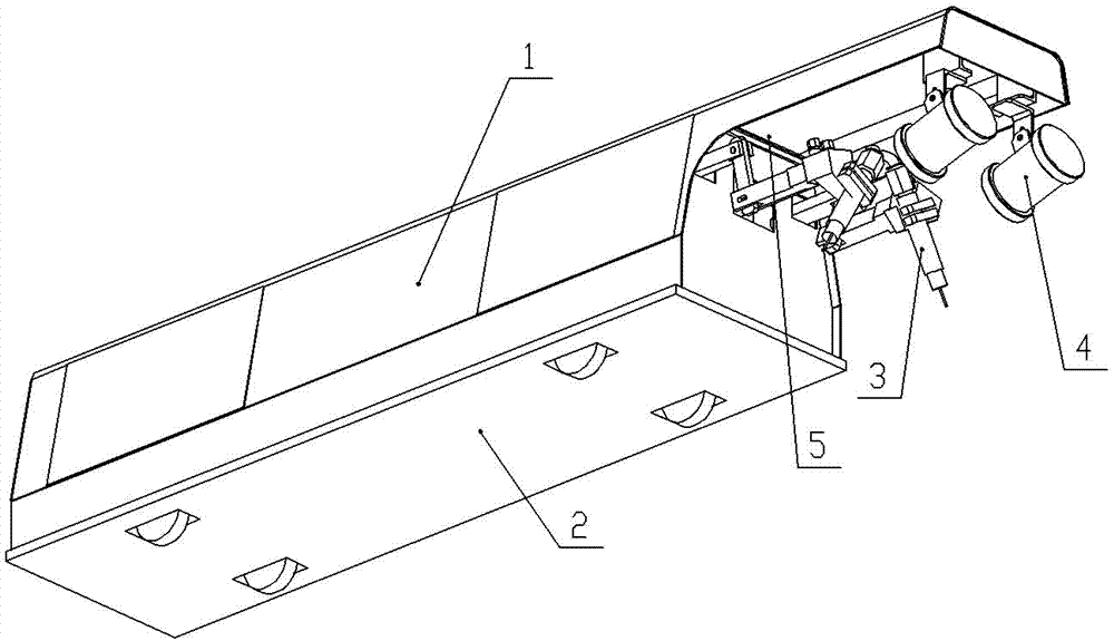
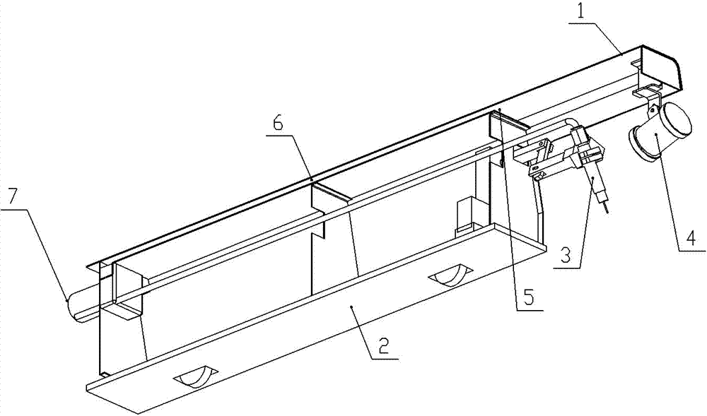
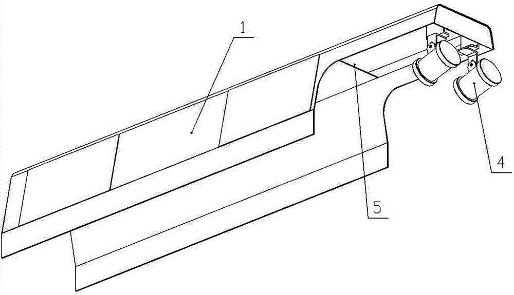
[0025] Please refer to Figure 1 to Figure 3 , figure 1 It is a three-dimensional structural schematic diagram of a specific embodiment of a U-rib internal welding welding fume treatment system provided by the present invention; figure 2 for figure 1 A three-dimensional sectional view of a U-rib internal welding welding fume treatment system cut from the middle; image 3 for figure 1 A three-dimensional schematic diagram of a U-rib internal welding welding fume treatment system with some components removed.

[0026] In a specific embodiment, the...


PUM


Abstract

The invention discloses a welding soot treatment system with an internally welded U rib for treating soot generated in the welding process. The welding soot treatment system comprises a discharge flue and an exhaust device, wherein the discharge flue is arranged on a shell of an internal welding machine; the discharge flue is provided with a soot inlet end and a sooth outlet end; and soot generated when the internal welding machine works can be inhaled from the sooth inlet end through the exhaust device and discharged from the sooth outlet end. The welding soot treatment system employing the mode is more compact in structure and does not additionally occupy the space, an operator does not need to operate through holding a pipe during working, meanwhile, the soot discharge effect is obvious, the problem of soot discharge of the internal welding machine is solved and normal working of an internal welding machine monitoring device is ensured. The invention further discloses the internal welding machine with the U rib.

Description

technical field [0001] The invention relates to the field of welding technology, in particular to a welding fume treatment system for U-rib internal welding. Background technique [0002] Steel box girder, also known as steel plate box girder, is a common structural form of long-span bridges and an important part of the bridge's load-bearing structure. It is mainly used to provide support and avoid bridge deformation. The steel box girder is mainly connected by the top plate, the bottom plate, etc. through full welding, and the top plate is generally a U-shaped rib structure, referred to as U rib. [0003] The internal welding machine is a device that can enter the inside of the U-rib and weld the inside of the U-rib. At the same time, it can realize a new welding method of the U-rib. It can weld the inside and outside of the U-rib on both sides, which improves the U-rib welding quality. The internal welding machine generally includes a mobile platform, a housing, a weldin...

Claims


Application Information

Patent Timeline
Patent Type & Authority Applications(China)
IPC IPC(8): B23K37/00B23K37/02
CPCB23K37/00B23K37/0247
Inventor 张华舒先庆叶君龙高兴李立明代钥沈俊杰
Owner WUCHUAN HEAVY ENG
Why Eureka
Try Eureka