Optical system for microcell spatial coherent pattern and operating method thereof

A technology of optical system and working method, which is applied in the field of optical system of micro-area spatial coherence pattern, and can solve problems such as measurement and acquisition

Active Publication Date: 2017-10-31
INST OF CHEM CHINESE ACAD OF SCI
View PDF4 Cites 0 Cited by
  • Summary
  • Abstract
  • Description
  • Claims
  • Application Information

AI Technical Summary

Problems solved by technology

However, there are two main challenges in the current microscopic system: 1) how to accurately select the two regions of interest for measurement; 2) how to collect the coherent pattern and measure the spectrum of the optical signals emitted from these two regions

Method used


Image

  • Optical system for microcell spatial coherent pattern and operating method thereof
  • Optical system for microcell spatial coherent pattern and operating method thereof
  • Optical system for microcell spatial coherent pattern and operating method thereof

Examples


Embodiment 1

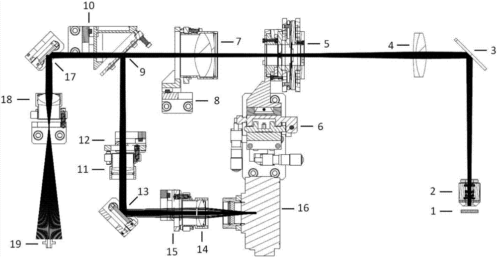
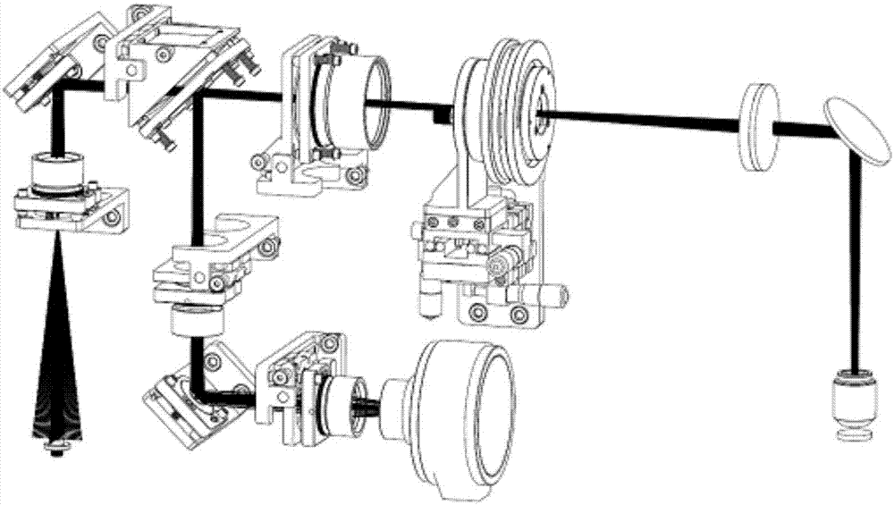
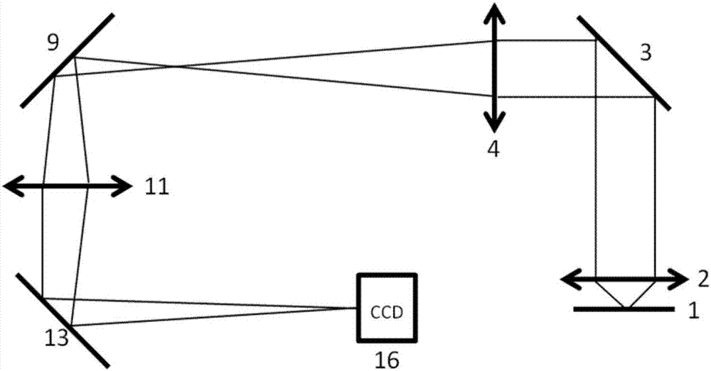
[0042] In this embodiment, the double-slit interference imaging lens 7 and the double-slit interference imaging lens 14 are moved out, the double-slit 5 is installed, and the total reflection mirror 9 and the imaging lens 11 are moved in, the optical system for the micro-area spatial coherence pattern Form the first light path, such as image 3 As shown, the first optical path is the monitoring imaging optical path, which mainly includes: microscope 2, total reflection mirror 3, lens 4, double slit 5, total reflection mirror 9, imaging lens 11, total reflection mirror 13, charge coupled device (CCD) 16, video output line and display screen (not shown in the figure). The microscope 2 collects the image of the sample 1 to be tested, and then passes through the total reflection mirror 3, the lens 4, the double slit 5, the total reflection mirror 9, the imaging lens 11, the total reflection mirror 13, and the charge-coupled device (CCD) 16. The video output line outputs the image...

Embodiment 2

[0044] In this embodiment, the imaging lens 11 is moved out, the double slit 5 is installed, and the double slit interference lens 7, the total reflection mirror 9 and the double slit interference lens 14 are moved in, and the optical system for the spatial coherence pattern of the micro-area forms the first Two optical paths, such as Figure 4 As shown, the second optical path mainly includes the following components: microscope 2, total reflection mirror 3, lens 4, double slit 5, double slit interference imaging lens 7, total reflection mirror 9, total reflection mirror 13, double slit interference imaging lens 14. Charge-coupled device (CCD) 16, video output line and display screen (not shown in the figure). The second optical path can realize the coherence test of the outgoing light of the two micro-regions selected by the double slit. If there is spatial coherence, interference fringes will be formed and imaged on the CCD, which can be observed through the display screen ...

Embodiment 3

[0047] In this embodiment, the double slit 5 is removed, the double slit interference imaging lens 7 and the total reflection mirror 9 are moved out, and the imaging lens 11 and the double slit interference lens 14 are moved in. light path, such as Figure 5 As shown, the third optical path mainly includes: a microscope 2 , a total reflection mirror 3 , a lens 4 , a total reflection mirror 17 , a lens 18 , and an optical fiber interface 19 . The third optical path can collect the microspectrum of the sample, and the light emitted from the microscope enters the signal output device and enters the free space to facilitate subsequent spectrum collection.

[0048] The optical paths given in the present invention are only exemplary descriptions, and optical path elements can also be added to each optical path as required to improve the quality of the optical path.

[0049] The present invention also proposes an imaging / spectrum sampling method for a micro-area spatial coherence pa...


PUM


Abstract

The invention relates to an optical system for a microcell spatial coherent pattern and an operating method thereof. The system comprises a microscope (2), a first total reflective mirror (3), a first lens (4), a double-slit unit (5), a first double-slit interference imaging lens (7), and a second total reflective mirror (9) that are arranged successively along an optical path. In addition, the system also includes an imaging lens (11), a third total reflective mirror (13), a second double-slit interference imaging lens (14), and a charge coupling device (16) that are arranged successively along the reflective optical path of the second total reflective mirror (9). The double-slit unit, the first double-slit interference imaging lens, the second total reflective mirror, the imaging lens, and the second double-slit interference imaging lens are movable elements. Different optical paths are formed by arranging or removing all movable elements at the optical path. In addition, the invention also provides an operating method of the system. With the method and system, with collection of the interference pattern, the spatial coherence and the coherent area of the light source under the micro-nano scale are measured, so that defects of the existing optical microscope system are overcome.

Description

technical field [0001] The invention relates to the field of optical imaging, in particular to an optical system for a micro-area spatial coherence pattern and a working method thereof. Background technique [0002] Light sources with spatial coherence have shown extremely important application values ​​in lighting, display, measurement, and information processing. The light source may have an unfixed phase difference in different regions of space. Only light waves within a certain spatial range have a relatively fixed phase difference, so that only light waves within a certain space are coherent. This feature is called spatial coherence of waves. . Studying the spatial coherence of light sources is not only beneficial to the design and preparation of high-quality coherent light sources with different structures and scales, but also conducive to the inverse study of the morphology and properties of luminescent substances through coherent properties. The typical device curr...

Claims


Application Information

Patent Timeline
IPC IPC(8): G02B27/00
Inventor 赵永生李勇军闫永丽
Owner INST OF CHEM CHINESE ACAD OF SCI
Why Eureka
Try Eureka