Immersion lithography system and immersion flow field maintaining method

A technology of immersion lithography and flow field, which is applied in the semiconductor field, can solve the problems of reduced efficiency of immersion lithography, and achieve the effect of improving lithography efficiency and saving time

Active Publication Date: 2017-10-31
SHANGHAI MICRO ELECTRONICS EQUIP (GRP) CO LTD
View PDF3 Cites 0 Cited by
  • Summary
  • Abstract
  • Description
  • Claims
  • Application Information

AI Technical Summary

Problems solved by technology

[0003] In the current immersion lithography system, after the exposure is completed, because the immersion liquid is filled between the silicon wafer and the projection objective lens, after the silicon wafer is moved out of the workbench, the immersion liquid will fall due to gravity, and the next unexposed silicon wafer will be uploaded Finally, the immersion liquid field needs to be re-established, that is, the immersion liquid is re-injected between the projection objective lens and the silicon wafer, and this process of continuously re-establishing the immersion liquid field reduces the efficiency of immersion lithography

Method used


Image

  • Immersion lithography system and immersion flow field maintaining method
  • Immersion lithography system and immersion flow field maintaining method
  • Immersion lithography system and immersion flow field maintaining method

Examples


Embodiment 1

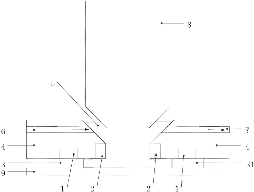
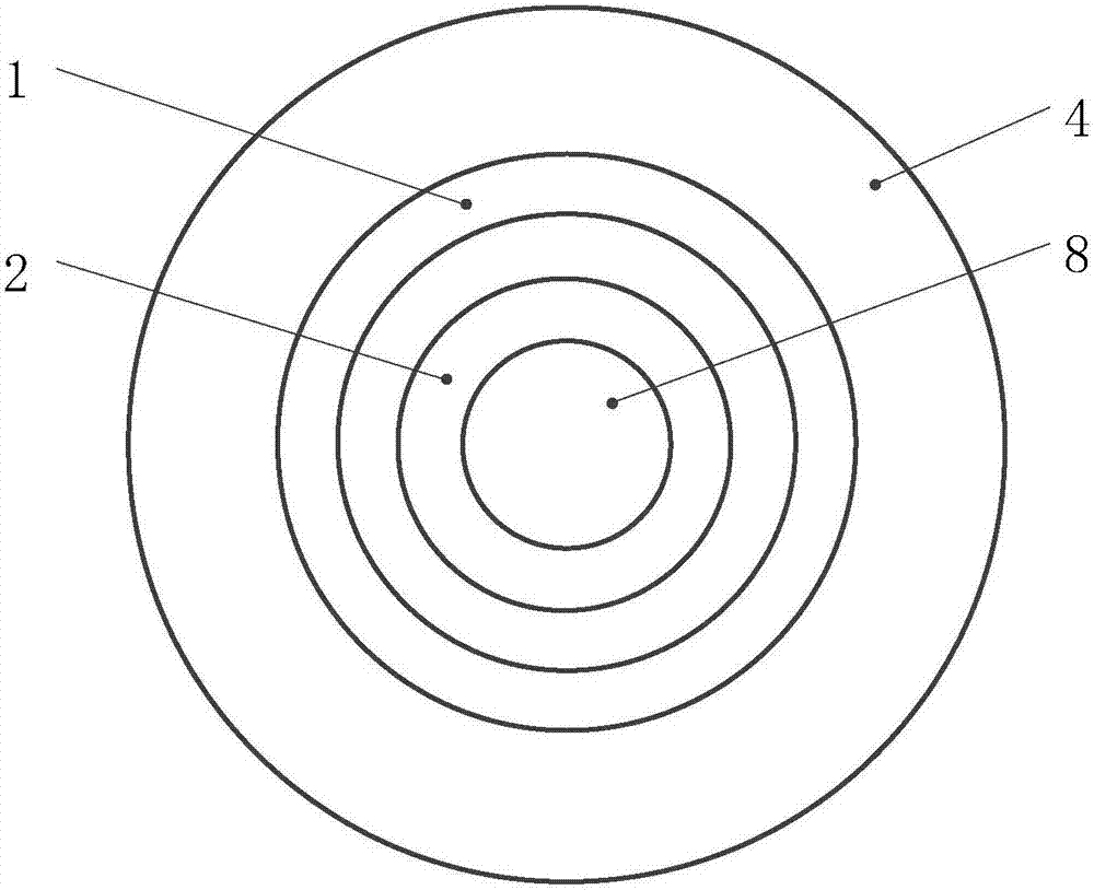
[0044] Please refer to figure 1 , the present invention provides an immersion lithography system, which is the same as the equipment in the traditional lithography system, except that an immersion device, that is, an immersion head 4, is placed between the projection objective lens 8 and the silicon wafer 9. In this embodiment, the immersion The section of the head 4 is circular, and the immersion liquid is placed in the immersion head 4 so that the bottom of the projection objective lens 8 and the upper surface of the silicon wafer 9 are in contact with the immersion liquid.

[0045] In this embodiment, the immersion liquid is a magnetic fluid, which is a stable colloidal solution, which is formed by uniformly dispersing nano-scale magnetic particles in a certain carrier liquid through a surfactant. It has solid magnetic properties and fluidity of the liquid. Since the magnetic fluid has a liquid behavior associated with superparamagnetism and saturation magnetization, it is...

Embodiment 2

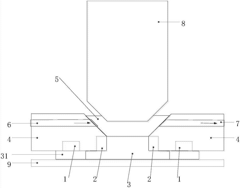
[0055] The difference between this embodiment and Embodiment 1 is that in step S3, the current of the first electromagnetic coil 1 and the second electromagnetic coil 2 is increased, so that all the liquid magnetic fluid 5 solidifies into a solid magnetic fluid 3, which enhances the photolithography system. Stability, to prevent unnecessary flow of the liquid magnetic fluid 5 due to ground vibration and other reasons.

[0056] In summary, the present invention provides an immersion liquid curing device and an immersion flow field maintenance method in the immersion device. During the exposure process, the immersion liquid curing device solidifies the immersion liquid between the immersion device and the silicon wafer 9 to form an annular wall 31 , the immersion device, the annular wall 31 and the silicon wafer 9 form a holding container and hold the immersion liquid, that is, the liquid magnetic fluid 5, and the immersion liquid in the annular wall 31 forms a liquid medium, and...


PUM


Abstract

The invention provides an immersion lithography system and an immersion flow field maintaining method. An immersion liquid curing apparatus is arranged in an immersion head; in an exposure process, the immersion liquid between the immersion head and a silicon wafer is cured to form a sealed wall by the immersion liquid curing apparatus; the immersion head, the sealed wall and the silicon wafer form an accommodating container for accommodating the immersion liquid; the immersion liquid in the sealed wall forms a medium; the immersion liquid field of the immersion liquid is maintained between a projection objective lens and the silicon wafer; after exposure is completed, all immersion liquid in contact with the silicon wafer is cured by the immersion liquid curing apparatus, so that after the silicon wafer is removed from a working table, the immersion liquid does not fall off due to gravity; after a new non-exposed silicon wafer is loaded on the working table, the cured immersion liquid is in contact with the silicon wafer, and next, the cured immersion liquid is liquefied by the immersion liquid curing apparatus to perform exposure of the next round. Therefore, by adoption of the apparatus and the process, re-building of the liquid field after replacement of the silicon wafer is not needed, so that time is saved and lithography efficiency is improved.

Description

technical field [0001] The invention relates to the field of semiconductors, in particular to an immersion photolithography system and an immersion flow field maintenance method. Background technique [0002] In the traditional lithography technology, the medium between the lens and the photoresist is air, while the so-called immersion lithography technology replaces the air medium with immersion liquid. In fact, the immersion lithography technology improves the resolution by shortening the wavelength of the light source after the light passes through the liquid medium, and the shortened magnification is the refractive index of the immersion liquid medium. Generally, a liquid with a high refractive index is filled between the lower surface of the last lens of the projection objective lens of the lithography machine and the photoresist on the silicon wafer. Wherein, the numerical aperture of the projection objective lens NA=n×sinθ, n is the refractive index of the medium bet...

Claims


Application Information

Patent Timeline
Patent Type & Authority Applications(China)
IPC IPC(8): G03F7/20
CPCG03F7/2041G03F7/70341
Inventor 丛国栋郑清泉吴立伟
Owner SHANGHAI MICRO ELECTRONICS EQUIP (GRP) CO LTD
Why Eureka
Try Eureka