

Variable-section-line hydraulic expansion tube torsion beam
A variable cross-section and torsion beam technology, applied in the field of vehicle parts, can solve the problems of low reliability and service life, improvement of torsion beam stress characteristics, stress concentration, etc., and achieve the effect of overall performance optimization and fatigue life improvement
- Summary
- Abstract
- Description
- Claims
- Application Information
AI Technical Summary
Problems solved by technology
Method used
Image

Examples
Embodiment 1
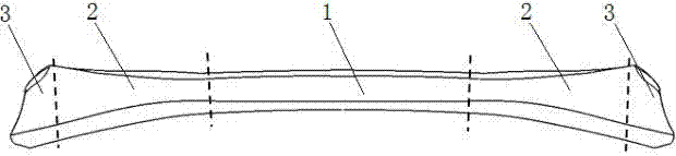
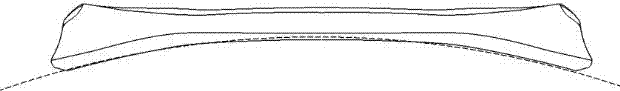
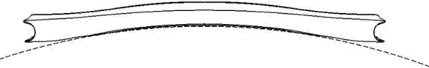
[0027] Such as figure 1 , 2 , 3, and 4, a variable-section line hydraulic expansion tube torsion beam is used as a part of the vehicle suspension, and is composed of an intermediate fixed section 1, a transition section 2 and an end connection section 3, and the intermediate fixed section 1 is located at In the middle position of the torsion beam, the end connecting section 3 is symmetrically located at both ends of the torsion beam, and the intermediate constant section section 1 and the end connecting section 3 are smoothly transitioned through the transition section 2, and the intermediate constant section section 1 The cross-section is double-layer V-shaped, and the end connecting section 3 is tubular; the length of the outermost cross-sectional contour line of the end connecting section 3 is longer than the cross-sectional contour line length of the middle constant section section 1 15% to 25% to increase the length of the weld seam in the connection area with the suspen...
PUM
| Property | Measurement | Unit |
|---|---|---|
| Arc radius | aaaaa | aaaaa |
| Height | aaaaa | aaaaa |
Abstract
Description
Claims
Application Information