Cascade type shaftless electric fan

An electric fan and grid-type technology, which is applied in the field of cascade-type shaftless electric fans, can solve problems such as unreasonable flow channel design, low energy conversion efficiency, and increased flow resistance, so as to achieve safety and not easily hurt people, and improve energy conversion efficiency , the effect of increasing the air volume

Inactive Publication Date: 2017-11-03
NORTHWESTERN POLYTECHNICAL UNIV +1
View PDF7 Cites 3 Cited by
  • Summary
  • Abstract
  • Description
  • Claims
  • Application Information

AI Technical Summary

Problems solved by technology

[0002] At present, the known bladeless fan has the advantages of more stable wind and soft wind force like natural wind. The mixing of high-energy fluid at the fan outlet and ambient low-energy fluid increases the air flow area in the direction of the outlet, making the incoming flow more uniform and larger. The area can be blown by the wind; but in comparison, the noise of the existing bladeless fan will be greater than that of the ordinary rotary blade fan when the air volume is large. The reasons are: 1. There are more noises from the inlet to the outlet. The design of flow parts and flow channels is unreasonable, and the energy conversion efficiency is low; 2. The diameter of the fan blade in the base is small. When

Method used


Image

  • Cascade type shaftless electric fan
  • Cascade type shaftless electric fan
  • Cascade type shaftless electric fan

Examples


Example Embodiment

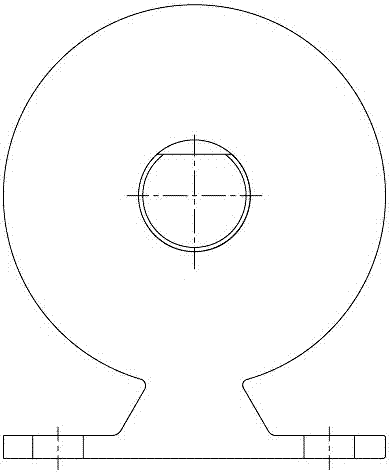
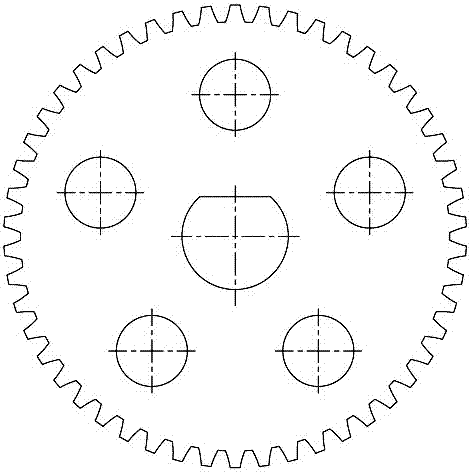
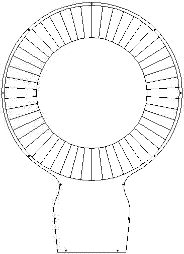
[0023] like Figure 1 to Figure 5 The shown cascade type shaftless electric fan includes a stator part, a rotor part, a rear cover plate 11 and a driving device; the stator part includes a mesh cover 2 and a casing 4, and the casing 4 includes an outer casing arranged in sequence in the radial direction 41. The static cascade 42 and the inner casing 43, the outer casing 41 and the inner casing 43 are all annular structures, and the multiple blades of the static cascade 42 are evenly distributed along the circumferential direction, and the outer casing 41 and the inner casing 43 pass through the static The blades of the cascade 42 are fixedly connected, and the net cover 2 is arranged on the inlet side of the outer casing 41 by screws 1; the rotor part is located in the space formed by the net cover 2 and the casing 4; the rotor part includes a rotating wheel 3 and a gear 8, and the rotating wheel 3 includes an outer ring 31, a moving blade cascade 32 and an inner ring 33 arran...


PUM


Abstract

The invention particularly relates to a cascade type shaftless electric fan which comprises a stator component, a rotor component and a driving device. The stator component comprises a mesh enclosure 2 and a shell 4, the shell 4 comprises an outer shell 41, a static cascade 42 and an inner shell 43 which are radially and sequentially arranged, the outer shell 41 and the inner shell 43 are fixedly connected by blades of the static cascade 42, the mesh enclosure 2 is arranged on an inlet side of the outer shell 41, the rotor component comprises a rotating wheel 3 and a gear 8, the rotating wheel 3 comprises an outer ring 31, a moving cascade 32 and an inner ring 33 which are radially and sequentially arranged, the outer ring 31 and the inner ring 33 are fixedly connected by blades of the moving cascade 32, the driving device drives the gear 8 to rotate, the gear 8 is engaged with the outer ring 31, the inner ring 33 is connected with the inner shell 43 through a bearing, and the runner center of the moving cascade 32 is overlapped with that of the static cascade 42. Air enters the moving cascade 32 from an inlet and then enters atmosphere through the static cascade 42, redundant flow passage components in the middle are omitted, runner design is reasonable, and energy conversion efficiency is improved.

Description

technical field [0001] The invention relates to the technical field of electric fans, in particular to a cascade-type shaftless electric fan. Background technique [0002] At present, the known bladeless fan has the advantages of more stable wind and soft wind force like natural wind. The mixing of high-energy fluid at the fan outlet and ambient low-energy fluid increases the air flow area in the direction of the outlet, making the incoming flow more uniform and larger. The area can be blown by the wind; but in comparison, the noise of the existing bladeless fan will be greater than that of the ordinary rotary blade fan when the air volume is large. The reasons are: 1. There are more noises from the inlet to the outlet. The design of flow parts and flow channels is unreasonable, and the energy conversion efficiency is low; 2. The diameter of the fan blade in the base is small. When a certain air volume must be guaranteed, the speed must be increased, resulting in increased n...

Claims


Application Information

Patent Timeline
IPC IPC(8): F04D25/08F04D29/40F04D29/70
CPCF04D25/08F04D29/403F04D29/703F04D19/002F04D25/02F04F5/16
Inventor 张森席德科李华星
Owner NORTHWESTERN POLYTECHNICAL UNIV
Why Eureka
Try Eureka