Electrical connection device

A technology for electrical connection devices and coils, applied in conductive connections, components of connection devices, connections, etc., can solve problems such as failure, affecting the maximum current value, large vibration, etc., achieve full and effective contact, and increase the number of contact points.

Pending Publication Date: 2017-11-03
易讯科技(苏州)有限公司
View PDF0 Cites 3 Cited by
  • Summary
  • Abstract
  • Description
  • Claims
  • Application Information

AI Technical Summary

Problems solved by technology

The more common ones are the charging piles of electric vehicles. The charging piles will provide a large current when they are working, and they have high requirements for the stability and reliability of current transmission. Currently, the existing charging piles generally use such as figure 1 and figure 2 As shown in this type of socket piece 1 and pin piece 2, the conduction between the two is realized by inserting the pin piece 2 into the socket piece 1, and a floating clamping shrapnel is set in the socket of the socket piece 1 3. To achieve electrical connection by clamping the pin part 2, but the contact points between the clamping spring 3 and the surface of the pin part 2 are relatively small, and it only covers a part of the surface of the pin part. This structure will It is easy to cause insufficient contact, which affects the maximum current value passed, especially when used in some harsh environments, such as strong vibration, thin air, or extreme heat and extreme cold conversion, it is easy to appear flashing phenomenon and cause connection failure
In addition, the existing processing technology of this kind of clamping shrapnel is all made of thin copper plate stamping, bending, welding, and shaping, which means that its material thickness is very limited, which also determines that it cannot pass through excessively large current, which limits its application in some high current scenarios

Method used


Image

  • Electrical connection device
  • Electrical connection device
  • Electrical connection device

Examples


Embodiment Construction

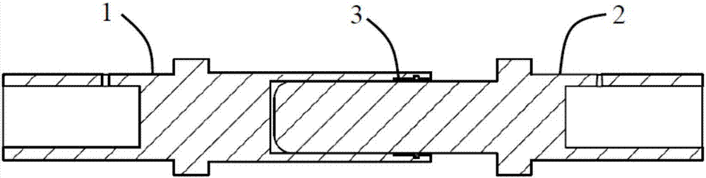
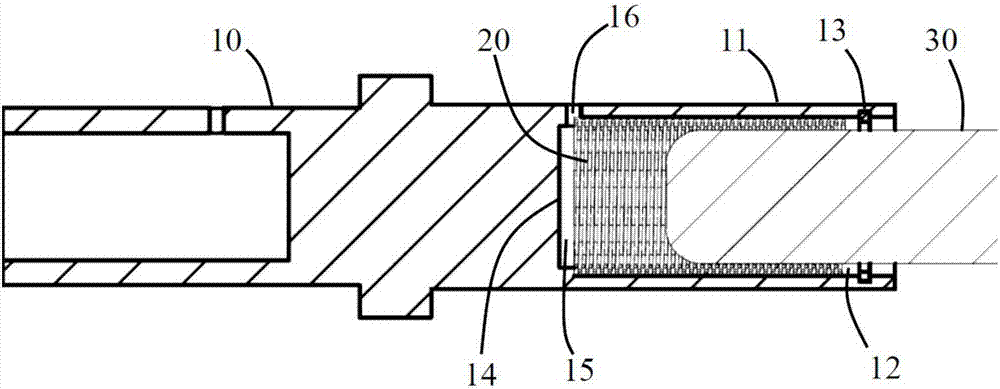
[0024] ginseng image 3 As shown, the present invention provides an electrical connection device, which is provided with a socket main body 10 and a spring member 20 located in the socket main body 10, the socket main body 10 and the spring member 20 are made of metal, The two are in contact with each other to realize conduction, and are used for electrical connection with a mating pin body 30. The pin body 30 is provided with an insertion end inserted into the inner side of the spring element 20, and the insertion end is inserted into the spring element. Conduction is realized under the clamping of 20.

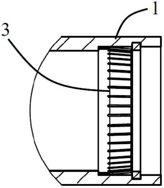
[0025] Wherein, the jack body 10 is in the shape of a strip, and one end thereof is provided with a ring wall 11 , an accommodation cavity 12 inside the ring wall 11 , and a retaining ring 13 inside the accommodation cavity 12 . The accommodating chamber 12 is cylindrical and is surrounded by the ring wall 11 for accommodating the spring member 20 , and the bottom wall 14 of...


PUM


Abstract

The present invention provides an electrical connection device, which is provided with a socket body and a spring member located in the socket body, the socket body is provided with a ring wall and an accommodating cavity surrounded by the ring wall, the The spring element is located in the accommodating cavity, and is provided with a first coil and a second coil contacting the ring wall. Compared with the prior art, the electrical connection device of the present invention arranges a spring member in the main body of the socket so that the spring member is sleeved on the main body of the pin and clamped and contacts with the main body of the pin, and the number of contact points is increased by using the spring member. The stability and reliability of the connection between the socket main body, the pin main body and the spring member are guaranteed, so that they can still maintain full and effective contact in an extreme vibration environment.

Description

technical field [0001] The invention relates to the field of electrical connection, in particular to an improved electrical connection device. Background technique [0002] In some high-current application scenarios, in order to ensure the stability and reliability of current transmission, electrical connection devices such as pins and sockets are usually used. Electrical equipment provides electricity. The more common ones are the charging piles of electric vehicles. The charging piles will provide a large current when they are working, and they have high requirements for the stability and reliability of current transmission. Currently, the existing charging piles generally use such as figure 1 and figure 2 As shown in this type of socket piece 1 and pin piece 2, the conduction between the two is realized by inserting the pin piece 2 into the socket piece 1, and a floating clamping shrapnel is set in the socket of the socket piece 1 3. To achieve electrical connection b...

Claims


Application Information

Patent Timeline
Patent Type & Authority Applications(China)
IPC IPC(8): H01R4/48H01R13/622
CPCH01R4/4863H01R13/622
Inventor 许海燕
Owner 易讯科技(苏州)有限公司
Why Eureka
Try Eureka