Supercharge Your Innovation With Domain-Expert AI Agents!

Spindle device special for valve element machining

A spindle device and valve core technology, applied in metal processing equipment, metal processing mechanical parts, manufacturing tools, etc., can solve problems such as deformation of valve core parts, and achieve the effect of improving the processing qualification rate and saving the installation time.

Pending Publication Date: 2017-11-07
朗快智能科技(杭州)有限公司
View PDF7 Cites 0 Cited by
  • Summary
  • Abstract
  • Description
  • Claims
  • Application Information

AI Technical Summary

Problems solved by technology

[0003] The technical problem to be solved by the present invention is to provide a special spindle device for spool processing, which can completely solve the problem of deformation of the spool parts clamped by the spindle chuck of the traditional lathe, meet the precision requirements of the spool parts, and improve the precision of the spool parts. The qualified rate of processing realizes the automatic clamping of valve core parts and saves the time of valve core parts clamping

Method used


Image

  • Spindle device special for valve element machining

Examples


Embodiment Construction

[0009] The preferred embodiments of the present invention are given below in conjunction with the accompanying drawings to describe the technical solution of the present invention in detail.

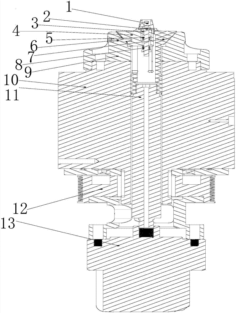
[0010] like figure 1 As shown, the special spindle device for spool processing of the present invention includes a thimble 2, a top sleeve 3, a bracket 4, an upper spring 5, a positioning screw 6, a ferrule 7, a lower spring 8, a fixed sleeve 9, a main shaft 10, a pull rod 11, and a pulley 12 , oil cylinder 13, at least one spool part 1 is located on the bracket 4 at the upper end of the main shaft 10, the thimble 2 is connected with the spool part 1 through the top sleeve 3, the upper spring 5 is located at the bottom of the top sleeve 3, and the positioning screw 6 is located on one side of the main shaft 10 side, the ferrule 7 is located on the other side of the main shaft 10, the lower spring 8 is located at the lower part of the bracket 4, the fixed sleeve 9 is located under the bra...


PUM


Abstract

The invention discloses a spindle device special for valve element machining. The spindle device comprises a centre, a top sleeve, a support, an upper spring, a locating screw, a clamp sleeve, a lower spring, a fixed sleeve, a spindle, a pull rod, a belt wheel and an oil cylinder. At least one valve element part is located on the support at the upper end of the spindle. The centre is connected with the valve element part through the top sleeve. The upper spring is located on the lower portion of the top sleeve. The locating screw is located on one side of the spindle. The clamp sleeve is located on the other side of the spindle. The lower spring is located on the lower portion of the support. The fixed sleeve is located below the support and fixes the spindle. The pull rod is located under the valve element part and partially located in the spindle. The belt wheel is arranged at the bottom of the spindle in a sleeving manner. The pull rod is connected with the oil cylinder. The spindle device can thoroughly solve the problem that valve element parts are clamped to deform by traditional lathe spindle chucks; the valve element part precision requirement is met; the machining percent of pass of the valve element part is improved; automatic clamping of the valve element part is achieved; and the clamping time of the valve element part is saved.

Description

technical field [0001] The invention relates to a spindle device, in particular to a special spindle device for valve core processing. Background technique [0002] At present, the precision of the valve core parts is getting higher and higher, and the straightness of the outer cone surface must be 0.002 mm and the roundness is more than 0.002 mm, and the demand for the valve core parts is very large. The processing machine tool for the outer cone surface of the valve core parts is generally For lathes, since the valve core parts are made of copper and the material is relatively soft, when using the spindle and chuck of a traditional lathe to clamp the valve core parts, the valve core parts are easily deformed, so that the machining accuracy of the parts cannot meet the requirements. The qualified rate of processing is very low. Moreover, due to the use of the spindle device of the traditional lathe, there is a lack of fixtures for automatic clamping of valve core parts, whi...

Claims


Application Information

Patent Timeline
IPC IPC(8): B23B19/02B23B31/30B23B31/10
CPCB23B31/10B23B31/302B23Q1/70
Inventor 李立强
Owner 朗快智能科技(杭州)有限公司
Features
  • R&D
  • Intellectual Property
  • Life Sciences
  • Materials
  • Tech Scout
  • Unparalleled Data Quality
  • Higher Quality Content
  • 60% Fewer Hallucinations
Learn More